EPSILON5-A1 Equinox Technologies, EPSILON5-A1 Datasheet - Page 66
EPSILON5-A1
Manufacturer Part Number
EPSILON5-A1
Description
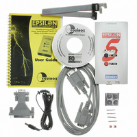
ISP PORTABLE PROGRAMMER USB
Manufacturer
Equinox Technologies
Series
Epsilon5r
Type
Portable ISPr
Specifications of EPSILON5-A1
Contents
Programmer, Software, Cables and Documentation
Ic Product Type
In-Circuit Programmer
Features
2Mbits Of On-Board Non-Volatile FLASH Memory For User Project Storage
Interface Type
JTAG
Mcu Supported Families
ATmega And AT91SAM7
Mpu Supported Families
AVR
Rohs Compliant
Yes
External Depth
31mm
Height
189mm
Length
80mm
For Use With/related Products
ATMEL AT89S, AVR, AT91SAM7, NXP P89C51Rx2 P89C66x, Zensys, Serial EEPROM's
Other names
483-1000


3.6.4 Set up instructions - Programmer and Target System independently
powered
The instructions below detail how to set up the programmer / Target System so that they are
independently powered.
Status LED key:
#
1
2
3
4
5
6
7a
7b
7c
8
EPSILON5 MKII Programmer - User Guide V1.12 – 1
Action
Remove programmer cover and remove
Jumper J9.
Ensure that the programmer is NOT
connected to the Target System via the ISP
Connector
Connect the ISP cable between correct ISP
Header on the programmer and the ISP
Header on the Target System.
Apply required voltage (3.0V to 5.0V DC) to
Con1 Power Connector from external Power
Supply.
Note – This voltage is NOT applied to the
Target System as J9 is removed.
Apply power to Target System from an
external supply (V_TVCC must be 3.1 – 5.0V)
Check the Target Vcc voltage (V_TVCC) is
3.1 – 5.0V using a volt meter
Press
There is no valid Programming Project in the
Programmer.
You need to upload a Programming
Project before using the programmer in
Standalone Mode.
There is a valid Programming Project in the
Programmer.
Remove power from programmer
button once
st
August 2007
Observation
This disconnects the
Programmer Vcc (from
Con1) to the Target Vcc.
All LED’s are OFF
Programmer and Target
system are NOT powered.
All LED’s are OFF
Programmer and Target
system are NOT powered
circuitry powers up to 3.0V
to V_TVCC
V_TVCC = 3.1 – 5.0V
Pressing any button will have
no effect.
‘Autoprogram Mode’.
Press the <YES> button
again to execute the
Programming Project.
Programmer internal
Target System powers up
Target Vcc LED illuminates
7a or 7b
FAIL LED starts flashing.
programmer is now in
All LED’s go out
Status of LED’s
55
Related parts for EPSILON5-A1
Image
Part Number
Description
Manufacturer
Datasheet
Request
R

Part Number:
Description:
CONVERTER KIT, COMMS, RS485
Manufacturer:
Equinox Technologies
Datasheet:

Part Number:
Description:
MOD PPM3 CONN-3 I/O ATMEGA JTAG
Manufacturer:
Equinox Technologies
Datasheet:

Part Number:
Description:
MODULE FOR PPM3-MK2 I/O DRIVER
Manufacturer:
Equinox Technologies
Datasheet:

Part Number:
Description:
MOD PPM3 SPECIAL FUNCTION DRIVER
Manufacturer:
Equinox Technologies

Part Number:
Description:
MODULE CONVERTER RS232 TO RS485
Manufacturer:
Equinox Technologies

Part Number:
Description:
MODULE CALCON FOR PPMS-MK2
Manufacturer:
Equinox Technologies
Datasheet:

Part Number:
Description:
ISP PORTABLE HS AVR JTAG USB
Manufacturer:
Equinox Technologies
Datasheet:

Part Number:
Description:
ISP PORTABLE HS AT91SAM7 USB
Manufacturer:
Equinox Technologies
Datasheet:

Part Number:
Description:
ISP PORTABLE USB AT91SAM7 UPGRAD
Manufacturer:
Equinox Technologies

Part Number:
Description:
PORTABLE PRODUCTION ISP HS USB
Manufacturer:
Equinox Technologies
Datasheet:

Part Number:
Description:
ISP MULTI PROJECT AVR JTAG USB
Manufacturer:
Equinox Technologies
Datasheet:

Part Number:
Description:
ISP MULTI PROJECT AT91SAM7 USB
Manufacturer:
Equinox Technologies
Datasheet:

Part Number:
Description:
ISP PRODUCTION PROGRAMMER
Manufacturer:
Equinox Technologies
Datasheet:

Part Number:
Description:
ISP PORTABLE AVR JTAG UPGRAD
Manufacturer:
Equinox Technologies
Datasheet:

Part Number:
Description:
PROGRAMMER PORTABLE HI-SPEED ISP
Manufacturer:
Equinox Technologies