PC7501 Renesas Electronics America, PC7501 Datasheet - Page 22
PC7501
Manufacturer Part Number
PC7501
Description
EMULATOR BASE UNIT M16C PLATFORM
Manufacturer
Renesas Electronics America
Type
Microcontrollerr
Datasheet
1.PC7501.pdf
(50 pages)
Specifications of PC7501
Contents
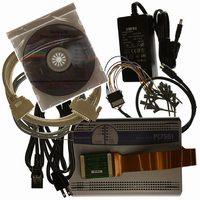
PC7501 Emulator, Cables, User Manual and CD-ROM
For Use With/related Products
M16C Family
For Use With
R0E521134EPB00 - KIT EMULATOR PROBE FOR PC7501R0E521000EPB00 - PROBE EMULATOR FOR PC7501
Lead Free Status / RoHS Status
Contains lead / RoHS non-compliant


PC7501 User’s Manual
3. External View
3.2.1 Interface Selection Switch
The emulator PC7501 allows you to specify one of three types of interfaces for communication with the host machine
as listed below.
(1) LPT parallel interface
(2) USB interface
(3) LAN interface
The interface selection switch is used to specify the type of communication interface available. The setting of the
interface selection switch is checked to see the available type after the emulator PC7501 is powered on or you press the
system reset switch.
Figure 3.4 shows the relationship between the interface selection switch settings and the interfaces recognized by the
emulator PC7501.
Figure 3.4 Relationship between interface selection switch and interfaces
3.2.2 LPT Parallel Interface Connector
The parallel interface cable is included. The LPT parallel interface connector is an IEEE 1284-C (36-pin half-pitch)
connector.
3.2.3 USB Interface Connector
The USB interface connector used for the emulator PC7501 is a USB interface cable (included) compliant with USB
1.1.
3.2.4 LAN Interface Connector
The LAN interface connector used for the emulator PC7501 is a 10BASE-T cable. As this product package does not
contain a 10BASE-T cable, get it separately.
To connect the emulator PC7501 directly to the host machine, use a cross cable. And, to connect the emulator PC7501
to the host machine via a HUB, use a straight cable.
3.2.5 Power Supply Switch
The power switch of the emulator PC7501 is used to turn the power on and off. Push the switch to the right position
(facing the rear panel) to turn on; push the switch to the left position to turn off.
3.2.6 DC Power Connector
The DC power connector connects the DC output connector of the AC adapter.
R20UT0207EJ0500 Rev.5.00
Page 22 of 50
Nov 01, 2010
Related parts for PC7501
Image
Part Number
Description
Manufacturer
Datasheet
Request
R

Part Number:
Description:
KIT STARTER FOR M16C/29
Manufacturer:
Renesas Electronics America
Datasheet:

Part Number:
Description:
KIT STARTER FOR R8C/2D
Manufacturer:
Renesas Electronics America
Datasheet:

Part Number:
Description:
R0K33062P STARTER KIT
Manufacturer:
Renesas Electronics America
Datasheet:

Part Number:
Description:
KIT STARTER FOR R8C/23 E8A
Manufacturer:
Renesas Electronics America
Datasheet:

Part Number:
Description:
KIT STARTER FOR R8C/25
Manufacturer:
Renesas Electronics America
Datasheet:

Part Number:
Description:
KIT STARTER H8S2456 SHARPE DSPLY
Manufacturer:
Renesas Electronics America
Datasheet:

Part Number:
Description:
KIT STARTER FOR R8C38C
Manufacturer:
Renesas Electronics America
Datasheet:

Part Number:
Description:
KIT STARTER FOR R8C35C
Manufacturer:
Renesas Electronics America
Datasheet:

Part Number:
Description:
KIT STARTER FOR R8CL3AC+LCD APPS
Manufacturer:
Renesas Electronics America
Datasheet:
Part Number:
Description:
KIT STARTER FOR RX610
Manufacturer:
Renesas Electronics America
Datasheet:

Part Number:
Description:
KIT STARTER FOR R32C/118
Manufacturer:
Renesas Electronics America
Datasheet:

Part Number:
Description:
KIT DEV RSK-R8C/26-29
Manufacturer:
Renesas Electronics America
Datasheet:

Part Number:
Description:
KIT STARTER FOR SH7124
Manufacturer:
Renesas Electronics America
Datasheet:

Part Number:
Description:
KIT STARTER FOR H8SX/1622
Manufacturer:
Renesas Electronics America
Datasheet:

Part Number:
Description:
KIT DEV FOR SH7203
Manufacturer:
Renesas Electronics America
Datasheet: