CBC5300-24C Cymbet Corporation, CBC5300-24C Datasheet - Page 3
CBC5300-24C
Manufacturer Part Number
CBC5300-24C
Description
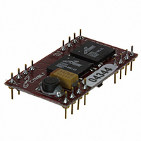
ENERCHIP EH CBC5300 MODULE
Manufacturer
Cymbet Corporation
Series
EnerChip™ EHr
Type
Energy Harvestingr
Datasheet
1.CBC5300-24C.pdf
(11 pages)
Specifications of CBC5300-24C
Module/board Type
Energy Harvesting Module
Input Voltage
0.25 V to 4 V
Output Voltage
3.6 V
Board Size
30.5 mm x 17.2 mm
Maximum Operating Temperature
+ 70 C
Minimum Operating Temperature
0 C
Product
Power Management Modules
Dimensions
30.5 mm x 17.2 mm
Lead Free Status / RoHS Status
Request inventory verification / Request inventory verification
For Use With/related Products
Thin Film Rechargeable Solid State Battery
Lead Free Status / Rohs Status
Lead free / RoHS Compliant
Other names
859-1000-5


Preliminary
Connecting the CBC5300 to the System
The CBC5300 board has two control lines that can be connected to a microcontroller (MCU) for the purpose of
conserving available energy, using incoming power efficiently, and extending EnerChip battery life. The table
below describes the functionality of the connector pins.
DS-72-06 Rev06
•
It provides power to the system according to the Operating Characteristics table shown below.
•
through an isolation pass transistor. The voltage on V
voltage at V
disconnectted from external circuits. In no event should V
power to a load.
•
be disconnected from the charging source of the CBC5300. This feature allows all available power to be
delivered to the load rather than to charging the EnerChips, a useful mode when limited transducer power
is available or when higher operating current is required from the system. When BATOFF is driven low, the
interaction between the charging source and the CBC5300 behaves normally. In other words, when BATOFF
is low the EnerChips will always be charging when sufficient input power is available.
•
»
EnerChips have been charged.
»
the boost converter and charge the EnerChips at peak rate, regardless of the state of charge of the
EnerChips. Programming an MCU timer to allow enough charging time to elapse after the assertion
of CHARGE will ensure that the EnerChips are fully charged before using them to deliver power to the
system. The advantage is that the system is then aware of the minimum reservoir of energy available in
the event transducer power goes to zero.
V
V
BATOFF is typically controlled by a microcontroller I/O line. When driven high, the on-board EnerChips will
CHARGE is an output signal from the CBC5300 that will be forced low under one of two conditions:
When transducer output power is very low, a low level on CHARGE indicates that the
CHARGE will also be driven low when transducer output power is more than sufficient to operate
OUT
BAT
is normally used for factory test purposes. It is indirectly connected to the on-board EnerChips
is the DC output voltage from the CBC5300 and is approximately 3.5V depending on load current.
UVLO SEL
OUT
CHARGE
SIGRTN
PGND
V
GATE
is one diode drop lower than the voltage on V
V
OPER
NPP
NPP
NPP
NPP
REG
©2009 Cymbet Corporation • Tel: +1-763-633-1780 • www.cymbet.com
V
IN
24-Pin DIP Module
1
2
3
4
5
6
7
8
9
10
11
12
23
22
20
19
18
15
13
24
21
17
16
14
GND
V
V
V
BATOFF
BATTEST
EC2GND
NPP
NPP
NPP
NPP
EC1GND
0UT
BAT
CAP
BAT
is connected to V
BAT
BAT
be used for any purpose other than to provide
Attribute
length
height
width
. It is recommended that V
CBC5300 Dimensions
EnerChip EH CBC5300
OUT
0.7 in [17.18mm]
1.2in [30.48mm]
0.9in [5.00mm]
by a diode and thus the
Size
BAT
remain
Page 3 of 11
Related parts for CBC5300-24C
Image
Part Number
Description
Manufacturer
Datasheet
Request
R


Part Number:
Description:
ENERCHIP CC EVAL KIT
Manufacturer:
Cymbet Corporation
Datasheet:

Part Number:
Description:
ENERCHIP CC SEH EVAL KIT
Manufacturer:
Cymbet Corporation
Datasheet:

Part Number:
Description:
ENERCHIP EP ENERGY HARVEST EVAL
Manufacturer:
Cymbet Corporation
Datasheet: