SUPERPRO280U(ROHS) Xeltek, SUPERPRO280U(ROHS) Datasheet - Page 37
SUPERPRO280U(ROHS)
Manufacturer Part Number
SUPERPRO280U(ROHS)
Description
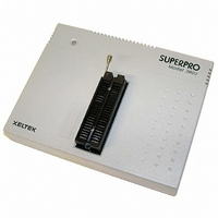
PROGRAMMER UNIVERSAL 48-PIN
Manufacturer
Xeltek
Series
SuperPro 280Ur
Type
Universalr
Datasheets
1.SUPERPRO580.pdf
(31 pages)
2.SUPERPROLXROHS.pdf
(58 pages)
3.SUPERPRO280UROHS.pdf
(218 pages)
Specifications of SUPERPRO280U(ROHS)
Contents
Programmer with 48-Dip Pin Socket, AC Adapter, Program CD, USB Cable, Users Guide and Power Supply
For Use With/related Products
E/EPROM, FLASH, PLD, Micros and more listed on Device Sheet, 22,000+ Devices Supported
For Use With
415-1029 - SOCKET ADAPTER FOR SDIP42415-1028 - SOCKET ADAPTER FOR TQFP32415-1027 - SOCKET ADAPTER FOR TSOP56415-1025 - SOCKET ADAPTER FOR SOIC20415-1024 - SOCKET ADAPTER FOR TSOP40415-1023 - SOCKET ADAPTER FOR SOP44415-1022 - SOCKET ADAPTER FOR TSOP56415-1019 - SOCKET ADAPTER FOR SOIC16/SOIC8415-1018 - SOCKET ADAPTER FOR SOIC28415-1015 - SOCKET ADAPTER FOR PLCC28415-1014 - SOCKET ADAPTER FOR PLCC20415-1013 - SOCKET ADAPTER FOR PLCC32415-1017 - SOCKET ADAPTER FOR PLCC44
Lead Free Status / RoHS Status
Lead free / RoHS Compliant
Other names
415-1032


The last 4 bytes of buffer data is:
FFC: 30 FFD: 30 FFE: 30 FFF: 31
If programming succeeds Operation Info screen displays:
Current AutoIncrement Data = 0002
The last 4 bytes of buffer data is:
FFC: 30 FFD: 30 FFE: 30 FFF: 32
Device
This selection allows users to program only utilize part of the chip, applicable to most E/EPROM (Flash)
device.
For example, MACRONIX MX29F200B TSOP48 is a 16 bit Flash device. Its program zone start and
end address is 0 and 1FFFF (Hex), and data buffer capacity is (1FFFF+1)*2=40000 (Hex,). Since it’s a
16-bit device, data buffer capacity is 2 times of that of the device. The default method is programming
from the start address to the end address. If user only wants to program the chip’s last part, please set the
start address to 10000 (Hex), and remain the end address default value. Thus the data for programming
are the data in data buffer between 20000 (Hex) and 40000 (Hex).
This function not only makes programming more flexible but also saves time under the Production
Mode.
Verify Mode
It is necessary to verify after the programming of a chip. According to the reference to the manufacture,
the requests of VCC voltage for verification are different.
1. Use VCC (+/- 5%) or (+/- 10%) to verify. For example, VCC=5.00V. Use VCC=5.00V to verify once,
or use VCC=4.74V and VCC =5.25V to verify twice (+/- 5%), or use VCC=4.50V and VCC=5.50V to
verify twice (+/- 10%).
2. Use MinVcc and MaxVcc to verify.
Note: The Operation Option will vary with the various devices. i.e. Most SCMs don’t allow user to set
the start and end address of the device.
4.1.4.2 Edit Auto
In the Edit Auto dialogue box, all devices have an Auto option, which is like a batch command. This
function allows the software auto operate in order displayed in the right column. For example, select
Related parts for SUPERPRO280U(ROHS)
Image
Part Number
Description
Manufacturer
Datasheet
Request
R

Part Number:
Description:
PROGRAMMER UNIVERSAL 48-PIN
Manufacturer:
Xeltek
Datasheet:


Part Number:
Description:
PROGRAMMER UNIVERSAL 48-PIN
Manufacturer:
Xeltek
Datasheet:

Part Number:
Description:
PROGRAMMER UNIVERSAL 48-PIN
Manufacturer:
Xeltek
Datasheet:

Part Number:
Description:
PROGRAMMER UNIV STANDALONE W/USB
Manufacturer:
Xeltek
Datasheet:


Part Number:
Description:
Device Programmer
Manufacturer:
Xeltek
Datasheet:

Part Number:
Description:
SUPERPRO 3000U IC Device Programmer In X4 CLUSTER
Manufacturer:
Xeltek

Part Number:
Description:
SOCKET ADAPTER FOR SOIC16/SOIC8
Manufacturer:
Xeltek
Datasheet:

Part Number:
Description:
Flash 256MB COMPACT FLASH CARD
Manufacturer:
Xeltek