101-1053 Rabbit Semiconductor, 101-1053 Datasheet - Page 16
101-1053
Manufacturer Part Number
101-1053
Description
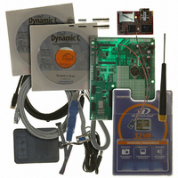
KIT DEV RABBITCORE RCM3365 US
Manufacturer
Rabbit Semiconductor
Series
RabbitCore 3000r
Type
MPU Core Moduler
Datasheet
1.20-101-1051.pdf
(164 pages)
Specifications of 101-1053
Contents
RabbitCore Module, Dev. Board, AC Adapter, Cable and Dynamic C® CD-Rom
Processor To Be Evaluated
RCM3365
Interface Type
Ethernet
Maximum Operating Temperature
+ 70 C
Operating Supply Voltage
3.15 V to 3.45 V
For Use With/related Products
RCM3365
Lead Free Status / RoHS Status
Lead free by exemption / RoHS compliant by exemption
Other names
316-1074


2.2 Hardware Connections
There are three steps to connecting the Prototyping Board for use with Dynamic C and the
sample programs:
1. Attach the RCM3365/RCM3375 module to the Prototyping Board.
2. Connect the serial programming cable between the RCM3365/RCM3375 and the worksta-
3. Connect the power supply to the Prototyping Board.
2.2.1 Step 1 — Attach Module to Prototyping Board
Turn the RCM3365/RCM3375 module so that the Ethernet jack is facing the direction shown
in Figure 2 below. Align the pins from headers J3 and J4 on the bottom side of the module into
header sockets JA and JB on the Prototyping Board. The picture card (NAND flash) does not
have to be inserted into connector J6 on the RCM3365/RCM3375 at this time.
Press the module’s pins firmly into the Prototyping Board header sockets—press down in the
area above the header pins using your thumbs or fingers over the header pins as shown in
Figure 2. Do not press down on the picture card connector (J6) unless the picture card is
installed, but rather press down on the circuit board along the edge by the connector. Also, do
not press down on the middle of the module to avoid flexing the module, which could damage
the module or components on the module.
Should you need to remove the module, grasp it with your fingers along the sides by the con-
nectors and gently work the module up to pull the pins away from the sockets where they are
installed. Do not remove the module by grasping it at the top and bottom.
10
tion PC or if you have an RCM3365 with RabbitSys firmware you may connect the
RCM3365 and the PC using Ethernet cables.
NOTE: It is important that you line up the pins on headers J3 and J4 of the RCM3365/
Figure 2. Install the RCM3365/RCM3375 Module on the Prototyping Board
RCM3375 module exactly with the corresponding pins of header sockets JA and JB on
the Prototyping Board. The header pins may become bent or damaged if the pin align-
ment is offset, and the module will not work. Permanent electrical damage to the mod-
ule may also result if a misaligned module is powered up.
RabbitCore RCM3365/RCM3375
Related parts for 101-1053
Image
Part Number
Description
Manufacturer
Datasheet
Request
R

Part Number:
Description:
KIT DEV STANDARD RCM5700
Manufacturer:
Rabbit Semiconductor
Datasheet:

Part Number:
Description:
BL4S200 TOOL KIT
Manufacturer:
Rabbit Semiconductor
Datasheet:


Part Number:
Description:
KIT DEV FOR BL2500 COYOTE
Manufacturer:
Rabbit Semiconductor
Datasheet:

Part Number:
Description:
Microcontroller Modules & Accessories Keypad/Display Unit 5V Panel Mount
Manufacturer:
Rabbit Semiconductor

Part Number:
Description:
Single Board Computers 24VDC/110 Power Supp
Manufacturer:
Rabbit Semiconductor
Part Number:
Description:
MODULE RABBITCORE RCM3720
Manufacturer:
Rabbit Semiconductor
Datasheet:
Part Number:
Description:
MODULE RABBITCORE RCM3220
Manufacturer:
Rabbit Semiconductor
Datasheet:
Part Number:
Description:
MODULE RABBITCORE RCM3210
Manufacturer:
Rabbit Semiconductor
Datasheet:
Part Number:
Description:
COMPUTER SGL-BOARD OP6600 W/SRAM
Manufacturer:
Rabbit Semiconductor
Datasheet:
Part Number:
Description:
COMPUTER SGL-BD BL2000 SRAM/FLSH
Manufacturer:
Rabbit Semiconductor