EVAL6599-400W-S STMicroelectronics, EVAL6599-400W-S Datasheet - Page 18
EVAL6599-400W-S
Manufacturer Part Number
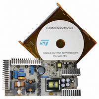
EVAL6599-400W-S
Description
DEMO BOARD FOR L6599
Manufacturer
STMicroelectronics
Type
Power Factor Correctionr
Specifications of EVAL6599-400W-S
Main Purpose
AC/DC, Primary Side and PFC
Outputs And Type
3, Isolated
Power - Output
400W
Voltage - Output
200V, 5V, 3.3V
Current - Output
2A, 1A, 700mA
Voltage - Input
90 ~ 264VAC
Regulator Topology
Resonant
Board Type
Fully Populated
Utilized Ic / Part
L6563, L6599
Input Voltage
90 V to 264 V
Output Voltage
3.3 V to 200 V
Dimensions
132 mm x 265 mm
Product
Power Management Modules
Lead Free Status / RoHS Status
Lead free / RoHS Compliant
For Use With/related Products
L6599
Other names
497-5856
Available stocks
Company
Part Number
Manufacturer
Quantity
Price


Application information
7.2
18/36
Operation at no load or very light load
When the resonant half-bridge is lightly loaded or unloaded at all, its switching frequency will
be at its maximum value. To keep the output voltage under control in these conditions and to
avoid losing soft-switching, there must be some significant residual current flowing through
the transformer's magnetizing inductance. This current, however, produces some
associated losses that prevent converter's no-load consumption from achieving very low
values.
To overcome this issue, the L6599 enables the designer to make the converter operate
intermittently (burst-mode operation), with a series of a few switching cycles spaced out by
long idle periods where both MOSFETs are in OFF-state, so that the average switching
frequency can be substantially reduced. As a result, the average value of the residual
magnetizing current and the associated losses will be considerably cut down, thus
facilitating the converter to comply with energy saving recommendations.
The device can be operated in burst-mode by using pin 5 (STBY): if the voltage applied to
this pin falls below 1.25 V the IC will enter an idle state where both gate-drive outputs are
low, the oscillator is stopped, the soft-start capacitor C
reference at RF
discharge. The IC will resume normal operation as the voltage on the pin exceeds 1.25 V by
50 mV.
To implement burst-mode operation the voltage applied to the STBY pin needs to be related
to the feedback loop.
input voltage range (e.g. when there is a PFC front-end).
Figure 24. Burst-mode implementation: narrow input voltage range
Figure 25. Burst-mode implementation: wide input voltage range
L6599
min
R
pin stays alive to minimize IC's consumption and V
Fmin
R
Fmin
Figure 24
R
Fmax
R
Fmax
shows the simplest implementation, suitable with a narrow
R
A
RFmin
STBY
RFmin
STBY
4
5
4
5
L6599
L6599
SS
R
keeps its charge and only the 2 V
B
R
A
+ R
7
B
>> R
LINE
C
CC
B+
R
Fmin
capacitor's
R
R
RC
RD
D
C
R
Fmax
L6599
Related parts for EVAL6599-400W-S
Image
Part Number
Description
Manufacturer
Datasheet
Request
R

Part Number:
Description:
EVAL BOARD FOR L6599
Manufacturer:
STMicroelectronics
Datasheet:

Part Number:
Description:
EVAL BOARD FOR L6599
Manufacturer:
STMicroelectronics
Datasheet:

Part Number:
Description:
DEMO BOARD FOR L6599
Manufacturer:
STMicroelectronics
Datasheet:

Part Number:
Description:
STMicroelectronics [RIPPLE-CARRY BINARY COUNTER/DIVIDERS]
Manufacturer:
STMicroelectronics
Datasheet:
Part Number:
Description:
STMicroelectronics [LIQUID-CRYSTAL DISPLAY DRIVERS]
Manufacturer:
STMicroelectronics
Datasheet:

Part Number:
Description:
BOARD EVAL FOR MEMS SENSORS
Manufacturer:
STMicroelectronics
Datasheet:
Part Number:
Description:
NPN TRANSISTOR POWER MODULE
Manufacturer:
STMicroelectronics
Datasheet:
Part Number:
Description:
TURBOSWITCH ULTRA-FAST HIGH VOLTAGE DIODE
Manufacturer:
STMicroelectronics
Datasheet:
Part Number:
Description:
Manufacturer:
STMicroelectronics
Datasheet:
Part Number:
Description:
DIODE / SCR MODULE
Manufacturer:
STMicroelectronics
Datasheet:
Part Number:
Description:
DIODE / SCR MODULE
Manufacturer:
STMicroelectronics
Datasheet:
Part Number:
Description:
Search -----> STE16N100
Manufacturer:
STMicroelectronics
Datasheet: