G9EA-1 DC24 Omron, G9EA-1 DC24 Datasheet - Page 7
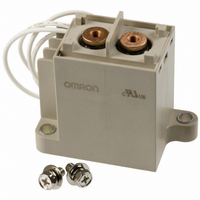
G9EA-1 DC24
Manufacturer Part Number
G9EA-1 DC24
Description
RELAY IND SPST 60ADC LEAD TERM
Manufacturer
Omron
Series
G9EA-1r
Specifications of G9EA-1 DC24
Relay Type
General Purpose
Coil Type
Standard
Contact Form
SPST-NO (1 Form A)
Contact Rating (current)
60A
Switching Voltage
400VDC - Max
Coil Current
208mA
Coil Voltage
24VDC
Turn On Voltage (max)
18 VDC
Turn Off Voltage (min)
1.92 VDC
Mounting Type
Chassis Mount
Termination Style
Wire Leads
Circuit
SPST-NO (1 Form A)
Contact Rating @ Voltage
60A @ 400VDC
Control On Voltage (max)
18 VDC
Control Off Voltage (min)
1.92 VDC
Coil Voltage Vdc Nom
24V
Contact Current Max
100A
Contact Voltage Dc Nom
400V
Coil Resistance
115.2ohm
Contact Configuration
SPST-NO
Current, Rating
60 A
Dielectric Rating
2500 VAC
Dimensions
2.87 " L x 1.42 " W x 2.64 " H
Function
Power
Material, Contact
Ag Alloy
Standards
UL, CSA
Termination
Leadwires
Voltage, Control
24 VDC
Voltage, Drop, On-state
0.1 V (Max.)
Voltage, Rating
400 VDC
Lead Free Status / RoHS Status
Lead free / RoHS Compliant
Lead Free Status / RoHS Status
Lead free / RoHS Compliant, Lead free / RoHS Compliant
Other names
G9EA-1-DC24
G9EA1 DC24
G9EA1DC24
Z1613
G9EA1 DC24
G9EA1DC24
Z1613


Precautions
■ Correct Use
Refer to the relevant catalog for common precautions.
1. Be sure to tighten all screws to the appropriate torque given
2. The G9EA and G9EC Relays’ contacts have polarity. Be sure to
3. Do not drop or disassemble this Relay. Not only may the Relay fail
4. Do not use these Relays in strong magnetic fields of 800 A/m or
5. This Relay is a device for switching high DC voltages. If it is used
6. If the Relay is used for no-load switching, the contact resistance
7. These Relays contain pressurized gas. Even in applications with
8. Do not use or store the Relay in a vacuum. Doing so will acceler-
9. With this Relay, if the rated voltage (or current) is continuously
10.The ripple percentage for DC relays can cause fluctuations in the
11.Ensure that a voltage exceeding the specified maximum voltage
12.Do not use the Relay at a switching voltage or current greater
Take measures to prevent contact with charged parts when using
the Relay for high voltages.
below. Loose screws may result in burning due to abnormal heat
generation during energization.
• M8 screws: 8.82 to 9.80 N·m
• M6 screws: 3.92 to 4.90 N·m
• M5 screws: 1.57 to 2.35 N·m
• M4 screws: 0.98 to 1.37 N·m
• M3.5 screws: 0.75 to 1.18 N·m
perform connections with the correct polarity. If the contacts are
connected with the reverse polarity, the switching characteristics
specified in this document cannot be assured.
to meet the performance specifications, it may also result in dam-
age, electric shock, or burning.
higher (e.g., near transformers or magnets). The arc discharge
that occurs during switching may be bent by the magnetic field,
resulting in flashover or insulation faults.
for voltages exceeding the specified range, it may not be possible
to interrupt the load and burning may result. In order to prevent
fire spreading, use a configuration in which the current load can
be interrupted in the event of emergencies.
In order to ensure safety of the system, replace the Relay on a
regular basis.
may increase and so confirm correct operation under the actual
operating conditions.
low switching frequencies, the ambient temperature and heat
caused by arc discharge in the contacts may allow permeation of
the sealed gas, resulting in arc interruption failure.
In order to ensure safety of the system, replace Relays on a regu-
lar basis.
ate deterioration of the sealing.
applied to the coil and contacts, and then turned OFF and imme-
diately ON again, the coil temperature, and consequently the coil
resistance, will be higher than usual. This means that the must-
operate voltage will also be higher than usual, exceeding the
rated value (“hot start”). In this case, take the appropriate counter-
measures, such as reducing the load current or restricting the
energizing time or ambient operating temperature.
must-operate voltage or humming. For this reason, reduce the rip-
ple percentage in full-wave rectified power supply circuits by add-
ing a smoothing capacitor. Ensure that the ripple percentage is
less than 5%.
is not continuously applied to the coil. Abnormal heating in the coil
may shorten the lifetime of the insulation coating.
than the specified maximum values. Doing so may result in arc
discharge interruption failure or burning due to abnormal heating
in the contacts.
!WARNING
DC Power Relays (60-A, 100-A Models)
13.The contact ratings are for resistive loads. The electrical endur-
14.Do not use the Relay in locations where water, solvents, chemi-
15.Be sure to turn OFF the power and confirm that there is no resid-
16.The distance between crimp terminals or other conductive parts
17.Use either a varistor, or a diode plus Zener diode as a protective
18.Do not tighten the screws to a torque exceeding 11 N•m for the
19.Be sure to use the screws provided with the product for wiring coil
The coil’s power consumption can be reduced by using in combina-
tion with a semiconductor circuit. Consult your OMRON representa-
tive for details.
Recommended Wire Size
Note: Use flexible leads.
G9EA-1(-B)
G9EA-1(-B)-CA
ance with inductive loads is inferior to that of resistive loads. Con-
firm correct operation under the actual operating conditions.
cals, or oil may come in contact with the case or terminals. Doing
so may result in deterioration of the case resin or abnormal heat-
ing due to corrosion or contamination of the terminals. Also, if
electrolyte adheres to the output terminals, electrolysis may occur
between the output terminals, resulting in corrosion of the termi-
nals or wiring disconnections.
ual voltage before replacing the Relay or performing wiring.
will be reduced and insulation properties will be lowered if wires
are laid in the same direction from the contact terminals. Use
insulating coverings, do not wire in the same direction, and take
other measures as required to maintain insulation properties.
circuit against reverse surge in the relay coil. Using a diode alone
will reduce the switching characteristics.
M8 screws and 5 N•m for the M5 screws.
Overtightening the contact terminals will reduce the switching per-
formance and damage the product.
terminals and contact terminals. The specified tightening torque
cannot be achieved with different screws and may result in abnor-
mal heat generation when energized.
Model
14 to 22 mm
22 to 38 mm
G9EA-1
Size
2
2
7
Related parts for G9EA-1 DC24
Image
Part Number
Description
Manufacturer
Datasheet
Request
R

Part Number:
Description:
DC Power Relay
Manufacturer:
Omron
Datasheet:
Part Number:
Description:
DC Power Relay
Manufacturer:
Omron
Datasheet:
Part Number:
Description:
DC Power Relay
Manufacturer:
Omron
Datasheet:
Part Number:
Description:
DC Power Relay
Manufacturer:
Omron
Datasheet:
Part Number:
Description:
DC Power Relay
Manufacturer:
Omron
Datasheet:

Part Number:
Description:
DC Power Relay
Manufacturer:
Omron
Datasheet:
Part Number:
Description:
DC Power Relay
Manufacturer:
Omron
Datasheet:
Part Number:
Description:
DC Power Relay
Manufacturer:
Omron
Datasheet:

Part Number:
Description:
DC POWER RELAY
Manufacturer:
Omron
Datasheet:
Part Number:
Description:
DC POWER RELAY
Manufacturer:
Omron
Datasheet:

Part Number:
Description:
DC POWER RELAY
Manufacturer:
Omron
Datasheet:

Part Number:
Description:
DC POWER RELAY
Manufacturer:
Omron
Datasheet:

Part Number:
Description:
RELAY IND SPST 60ADC LEAD TERM
Manufacturer:
Omron
Datasheet:
Part Number:
Description:
DC Power Relay
Manufacturer:
Omron
Datasheet:
Part Number:
Description:
DC Power Relay
Manufacturer:
Omron
Datasheet: