SF4D-DC24V Panasonic Electric Works, SF4D-DC24V Datasheet - Page 6
SF4D-DC24V
Manufacturer Part Number
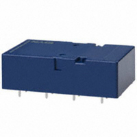
SF4D-DC24V
Description
RELAY SAFETY 6A 24VDC PCMNT 8PST
Manufacturer
Panasonic Electric Works
Series
SFr
Type
Safety Relayr
Specifications of SF4D-DC24V
Relay Type
Safety
Contact Form
8PST (4 Form A, 4 Form B)
Contact Rating (current)
6A
Switching Voltage
250VAC
Coil Type
Standard
Coil Current
20.8mA
Coil Voltage
24VDC
Turn On Voltage (max)
14.4 VDC
Turn Off Voltage (min)
3.6 VDC
Mounting Type
Through Hole
Termination Style
PC Pin
Circuit
8PST (4 Form A, 4 Form B)
Contact Rating @ Voltage
6A @ 250VAC
Control On Voltage (max)
14.4 VDC
Control Off Voltage (min)
3.6 VDC
Brand/series
SF Series
Current, Rating
6 A
Function
Safety
Material, Contact
Gold-Flashed Silver Alloy
Number Of Pins
18
Resistance, Coil
1.152 Ohms
Standards
cULus, TUV, CSA
Temperature, Operating
-40 to +70 °C
Termination
Solder
Voltage, Breakdown
2500 V (RMS) (Between Contacts and Coil)
Voltage, Control
24 VDC
Voltage, Rating
380 VAC
Weight
1.66 Oz. (Approx.)
Relay Construction
Non-Latching
Contact Arrangement
4PST-NO/4PST-NC
Coil Voltage Dc
24V
Voltage Rating (vdc)
30V
Voltage Rating (vac)
440V
Dropout Volt (min)
3.6VDCV
Coil Resistance
1.152kohm
Pick-up Voltage (max)
18VDC
Maximum Power Rating
180W/1.5KVA
Operate Time
30ms
Contact Current Rating
6A
Contact Material
Silver Tin Oxide/Gold Flash
Coil Suppression Diode
No
Push To Test Button
No
Led Indicator
No
Seal
Unsealed
Product Height (mm)
16.5mm
Product Depth (mm)
33mm
Product Length (mm)
53.3mm
Operating Temp Range
-40C to 70C
Pin Count
18
Mounting Style
Through Hole
Lead Free Status / RoHS Status
Lead free / RoHS Compliant
Other names
255-1441
Available stocks
Company
Part Number
Manufacturer
Quantity
Price


2) 4 Form A 4 Form B type
When internal contacts (No. 2, No. 3, No. 6 or No. 7) are welded, the armature becomes non-operational and the four form “a” contact
gaps are maintained at 0.5 mm
When external contacts (No. 1, No. 4, No. 5 or No. 8) are welded, gaps of 0.5 mm
adjacent contacts and other contacts operate normally by the coil being non-energized.
Example 2:
If external connections are made in series.
Even if one of the contacts welds, the other contacts
operate independently and the contact gaps are
maintained at greater than 0.5 mm
For Cautions for Use.
No.8
No.7
No.6
No.5
No.8
No.6
No.8
No.7
No.6
No.5
No.7
No.5
Terminal No. 20–19 12–11 8–7 16–15
Contact No.
Contact Operation Table
External Contacts Weld
Internal Contacts Weld
No.1 No.2 No.3 No.4
Non-energized
Energized
13–14 5–6 9–10 17–18
No.5 No.6 No.7 No.8
.020
inch.
.020inch
All Rights Reserved © COPYRIGHT Panasonic Electric Works Co., Ltd.
No.1
No.2
No.3
No.4
No.1
No.3
No.1
No.2
No.3
No.4
No.2
No.4
or greater. Reliable cut-off is thus ensured.
The table below shows the state of the other contacts when the current through
the welded form “a” contact is 0 V and the rated voltage is applied through the
form “b” contact.
* Contact gaps are shown at the initial state.
Non-energized
Contact No.
If the contacts change state owing to loading/breaking it is necessary to check
the actual loading.
No.8
No.6
No.8
No.6
terminal
No.7
No.5
No.7
No.5
Welded
Non-energized (when no. 1 contact is welded)
No.
Energized (when no. 2 contact is welded)
Energized
Contact No.
1
2
3
4
5
6
7
8
>0.5
>0.5
>0.5
>0.5
1
Weld
>0.5
>0.5
>0.5
>0.5
>0.5
2
>0.5
>0.5
>0.5
>0.5
>0.5
3
State of other contacts
>0.5
>0.5
>0.5
4
No.1
No.3
No.1
No.2
No.3
No.4
No.2
No.4
.020inch
Contact gap
min 0.5 mm
>0.5
>0.5
>0.5
5
Example: If the No. 2 contact welds.
Each of the four form “a” contacts (No. 1, 3, 5, and 7)
maintains a gap of greater than 0.5 mm
Example 1: If the No. 1 contact welds.
The adjacent No. 2 contact maintains a gap of greater
than 0.5 mm
the coil is not energized, return to their normal return
state; each of form “a” contacts (No. 3, 5, and 7)
maintains a contact gap of greater than 0.5 mm
.020
8) return to a closed state.
and greater are maintained between
SF Double contact type
>0.5
>0.5
>0.5
>0.5
>0.5
6
.020 inch
inch; each of the form “b” contacts (No. 4, 6, and
>0.5
>0.5
>0.5
>0.5
>0.5
7
.020
>0.5
>0.5
>0.5
inch. The other contacts, because
8
>0.5: contact gap is kept at
min. 0.5 mm
Empty cells:
either closed or open
: contact closed
.020 inch
.020
inch.
Related parts for SF4D-DC24V
Image
Part Number
Description
Manufacturer
Datasheet
Request
R

Part Number:
Description:
SF4D (4a4b)
Manufacturer:
PANASONIC EW
Datasheet:
Part Number:
Description:
SF4d (4a4b)
Manufacturer:
PANASONIC EW
Datasheet:
Part Number:
Description:
SF4D (4a4b)
Manufacturer:
PANASONIC EW
Datasheet:

Part Number:
Description:
RELAY SAFETY 6A 12VDC PCMNT 8PST
Manufacturer:
Panasonic Electric Works
Datasheet:

Part Number:
Description:
Manufacturer:
Panasonic Electric Works
Datasheet:
Part Number:
Description:
Manufacturer:
Panasonic Electric Works
Datasheet:

Part Number:
Description:
CONN SOCKET P4 .4MM 50POS SMD
Manufacturer:
Panasonic Electric Works
Datasheet:
Part Number:
Description:
CONN SOCKET .8MM 16POS SMD
Manufacturer:
Panasonic Electric Works
Datasheet:
Part Number:
Description:
CONN HEADER .8MM 16POS SMD
Manufacturer:
Panasonic Electric Works
Datasheet:
Part Number:
Description:
CONN SOCKET .8MM 20POS SMD
Manufacturer:
Panasonic Electric Works
Datasheet:
Part Number:
Description:
CONN SOCKET .8MM 20POS SMD
Manufacturer:
Panasonic Electric Works
Datasheet:
Part Number:
Description:
CONN HEADER .8MM 20POS SMD
Manufacturer:
Panasonic Electric Works
Datasheet:
Part Number:
Description:
CONN SOCKET .8MM 22POS SMD
Manufacturer:
Panasonic Electric Works
Datasheet:
Part Number:
Description:
CONN SOCKET .8MM 30POS SMD
Manufacturer:
Panasonic Electric Works
Datasheet: