AEV19012W Panasonic Electric Works, AEV19012W Datasheet - Page 8
AEV19012W
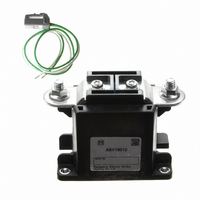
Manufacturer Part Number
AEV19012W
Description
RELAY INDUSTRIAL SPST 300A 12VDC
Manufacturer
Panasonic Electric Works
Series
AEVr
Datasheet
1.AEV804.pdf
(8 pages)
Specifications of AEV19012W
Relay Type
Automotive
Contact Form
SPST-NO (1 Form A)
Contact Rating (current)
300A
Switching Voltage
400VDC
Coil Type
Standard
Coil Current
3.2A
Coil Voltage
12VDC
Turn On Voltage (max)
9 VDC
Turn Off Voltage (min)
2 VDC
Mounting Type
Chassis Mount
Termination Style
Screw Terminal
Circuit
SPST-NO (1 Form A)
Contact Rating @ Voltage
300A @ 400VDC
Control On Voltage (max)
9 VDC
Control Off Voltage (min)
2 VDC
Lead Free Status / RoHS Status
Lead free / RoHS Compliant
Other names
255-2581
Available stocks
Company
Part Number
Manufacturer
Quantity
Price

Part Number:
AEV19012W
Manufacturer:
PANASONIC/松下
Quantity:
20 000


EV (AEV)
NOTES
1. For general cautions for use, please
refer to the “General Application
Guidelines”.
2. When installing the relay, always
use washers to prevent the screws
from loosening.
Tighten each screw within the rated
range given below. Exceeding the
maximum torque may result in breakage.
Mounting is possible in either direction.
<Relay installing section>
• M4 screw (for 10A type): 1.8 to 2.7 N·m
• M5 screw (for 20A, 80A, 120A and 300A
types): 3 to 4 N·m
<Main terminal installing section>
• M5 nut (for 80A type): 3 to 4 N·m
• M6 nut (for 120A type): 6 to 8 N·m
• M8 nut (for 300A type): 10 to 12 N·m
3. The coils (300 A type) and contacts
(all type) of the relay are polarized, so
follow the connection schematic when
connecting the coils and contacts.
Type 300 A contains a reverse surge
voltage absorption circuit; therefore a
surge protector is not needed. We
recommend installing a surge protector
varistor (ZNR) for the 10A, 20A, 80A and
120A types.
<Recommend varistor>
Amount of proof energy: Min. 1 J
Varistor voltage: 1.5 to 2.0 times of
nominal voltage
Avoid using a diode as this may result in
decreased cut-off capability.
4. As a general rule, do not use a relay
if it has been dropped.
5. Avoid mounting the relay in strong
magnetic fields (near a transformer or
magnet) or close to an object that
radiates heat.
6. Electrical life
This relay is a high-voltage direct-current
switch. In its final breakdown mode, it
may lose the ability to provide the proper
cut-off. Therefore, do not exceed the
indicated switching capacity and life.
(Please treat the relay as a product with
limited life and replace it when
necessary.)
In the event that the relay loses cut-off
ability, there is a possibility that burning
may spread to surrounding parts, so
configure the layout so that the power is
turned off within one second.
All Rights Reserved © COPYRIGHT Panasonic Electric Works Co., Ltd.
7. Permeation life of internal gas
This relay uses a hermetically encased
contact (capsule contact) with gas inside.
The gas has a permeation life that is
affected by the temperature inside the
capsule contact (ambient temperature +
temperature rise due to flow of electrical
current). For this reason, make sure the
ambient operating temperature is
between –40 and 80°C
(300A type is Max. 85°C 185°F), and the
ambient storage temperature is between
–40 and 85°C
8. If the power is turned off and then
immediately on after applying the
rated voltage (current) continuously to
the relay’s coil and contact, the
resistance of the coil will increase due
to a rise in the coil temperature.
This causes the pick-up voltage to
rise, and possibly exceed the rated
pick-up voltage. In these
circumstances, take measures such
as reducing the load current, limiting
the duration of current flow, and
applying a coil voltage higher than the
rated operating voltage.
9. Main contact ratings in the ratings
apply to when there is a resistive load.
If you are using an inductive load
(L load) such that L/R > 1 ms, add
surge protection in parallel with the
inductive load.
If this is not done, the electrical life
will decrease and cut-off failure may
occur.
10. For the 300 A type, drive the coil
with a quick startup.
(Built-in one-shot pulse generator
circuit)
11. Be careful that foreign matter and
oils and fats kind don’t stick to the
main terminal parts because it is likely
to cause terminal parts to give off
unusual heat.
Also, please use the following
materials for connected harnesses
and bus bars.
10A type: Min. 2 mm
sectional area
20A type: Min. 3 mm
sectional area
80A type: Min. 15 mm
sectional area
120A type: Min. 38 mm
sectional area
300A type: Min. 100 mm
sectional area
–40 and
2
2
2
nominal cross-
nominal cross-
nominal cross-
2
+185°F.
–40 and +176°F
2
nominal cross-
nominal cross-
12. As a guide, the insertion strength
of the plug-in terminal into the relay
tab terminal should be 40 to 70N (10A
type), 40 to 80N (20A type). Please
select a plug-in terminal (flat
connection terminal) which comply
with JIS C2809-1992.
10A type: for plate thickness 0.5mm and
#187 tab terminal
20A type: for plate thickness 0.8mm and
#250 tab terminal
13. Avoid excessive load applied to
the terminal in case of installing such
as a bus bar etc., Because it might
adversely affect the opening and
closing performance.
14. Use the specified connector for the
connector terminal connection (80A,
120A and 300A)
Yazaki Corporation 7283 – 1020 or
equivalent
15. After the ON signal enters the 300A
type, automatic coil current switching
occurs after approximately 0.1
seconds. Do not repeatedly turn it OFF
within that 0.1 seconds interval, as
doing so may damage the relay.
Related parts for AEV19012W
Image
Part Number
Description
Manufacturer
Datasheet
Request
R

Part Number:
Description:
RELAY INDUSTRL SPST-NO 80A 12VDC
Manufacturer:
Panasonic Electric Works
Datasheet:

Part Number:
Description:
RELAY INDUSTRL SPST-NO 80A 24VDC
Manufacturer:
Panasonic Electric Works
Datasheet:

Part Number:
Description:
RELAY INDUSTRIAL SPST 300A 24VDC
Manufacturer:
Panasonic Electric Works
Datasheet:

Part Number:
Description:
RELAY PWR MINI 80A 12VDC SCREW
Manufacturer:
Panasonic Electric Works
Datasheet:
Part Number:
Description:
RELAY PWR MINI 30A 12VDC SCREW
Manufacturer:
Panasonic Electric Works
Datasheet:
Part Number:
Description:
RELAY PWR MINI 150A 12VDC SCREW
Manufacturer:
Panasonic Electric Works
Datasheet:
Part Number:
Description:
RELAY PWR MINI 60A 12VDC SCREW
Manufacturer:
Panasonic Electric Works
Datasheet:
Part Number:
Description:
RELAY PWR MINI 60A 24VDC SCREW
Manufacturer:
Panasonic Electric Works
Datasheet:
Part Number:
Description:
RELAY PWR MINI 150A 12VDC SCREW
Manufacturer:
Panasonic Electric Works
Datasheet:
Part Number:
Description:
Manufacturer:
Panasonic Electric Works
Datasheet:
Part Number:
Description:
Manufacturer:
Panasonic Electric Works
Datasheet:

Part Number:
Description:
CONN SOCKET P4 .4MM 50POS SMD
Manufacturer:
Panasonic Electric Works
Datasheet:
Part Number:
Description:
CONN SOCKET .8MM 16POS SMD
Manufacturer:
Panasonic Electric Works
Datasheet:
Part Number:
Description:
CONN HEADER .8MM 16POS SMD
Manufacturer:
Panasonic Electric Works
Datasheet:
Part Number:
Description:
CONN SOCKET .8MM 20POS SMD
Manufacturer:
Panasonic Electric Works
Datasheet: