LT4H-DC24VS Panasonic Electric Works, LT4H-DC24VS Datasheet - Page 14
LT4H-DC24VS
Manufacturer Part Number
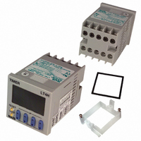
LT4H-DC24VS
Description
TIMER RELAY DIG 24VDC SCREW TERM
Manufacturer
Panasonic Electric Works
Series
LT4Hr
Datasheet
1.LT4H-DC24VS.pdf
(39 pages)
Specifications of LT4H-DC24VS
Lead Free Status / RoHS Status
Lead free / RoHS Compliant
Other names
255-1217


LT4H-W
OPERATION MODE
46
ON-start flicker
and notes
OFF-start
Remarks
one shot
Delayed
flicker
A
B
C
• The pulse input mode starts the operation by starting the
• When using the unit by starting it with the power on, short-
• Each signal input such as start, reset, stop and lock inputs is applied by short-circuiting its input terminal and common terminal
• The 8-pin type does not have a stop input or lock input.
• Elapsed value cleared when power is turned on.
• Time limit start initiated when start input goes on; start input ignored if time limit interval
• Elapsed value cleared when one operation has been completed.
• Elapsed value cleared when power is turned on.
• Time limit start initiated when start input goes on; start input ignored if time limit interval
• Elapsed value cleared when power is turned on.
• Time limit start initiated when start input goes on; start input ignored if time limit interval
start input.
circuit the start terminal (8-pin: Q to R, 11-pin: E to Y and
screw terminal:
(8-pin type: terminal Q, 11-pin type: terminal E and screw terminal: terminal
is in progress.
is in progress.
is in progress.
Power
supply
Output
Stop
Reset
Start
Power
supply
Output
Stop
Reset
Start
Power
supply
Output
Stop
Reset
Start
PULSE
PULSE
PULSE
T1
T1
T1
B
C
T2
T2
OFF-start/repeating operation t
ON-start/repeating operation t
6
A
T1
T2
T1
PULSE
to
OFF-start/1 operation t
T2
T2
9
ta
ta
).
tb tc
ta
tb
: Pulse input
tc
tb
td t1
td t1
tc
td
T1
T1 t2
ta+tb=T1
ta+tb=T1
ta+tb=T1
t2
t1
1
<T
T1 t2
tc+td=T2
tc+td=T2
1
tc+td=T2
1
1
, t
<T
<T
2
<T
1
1
, t
, t
2
2
2
<T
<T
2
2
• The integrating input mode is operated by the integrated
time of the start input. In other word, the timer operates only
when the start input is performed.
• When the elapsed value is cleared by the reset input, the
output is reset.
• When using the unit by starting it with the power on, short-
circuit the start terminal (8-pin: Q to R, 11-pin: E to Y and
screw terminal:
• Elapsed value not cleared when power is turned on (power failure backup function).
• When power is turned back on, same status is maintained for output as that previous
• Elapsed value cleared when one operation has been completed.
• Elapsed value not cleared when power is turned on (power failure backup function).
• When power is turned back on, same status is maintained for output as that previous
• Elapsed value not cleared when power is turned on (power failure backup function).
• When power is turned back on, same status is maintained for output as that previous
INTEGRATION
INTEGRATION
to power going off.
to power going off.
to power going off.
Power
supply
Output
Stop
Reset
Start
Power
supply
Output
Stop
Reset
Start
Power
supply
Output
Stop
Reset
Start
INTEGRATION
ta
ta
ta
6
INTEGRATION
) respectively.
6
tb
tb
tb
B
tc
tc
C
tc
to
OFF-start/repeating operation t
ON-start/repeating operation t
td
td te
A
td
9
te
).
OFF-start/1 operation t
tf tg
tf tg
te
: Integrating input
tf tg
th
ta+tb=T1
th T1
ta+tb=T1
ta+tb=T1
T1
th
T2
T2
tc+td=T2
tc+td=T2
tc+td=T2
t1
t1
t1
T1
T1
T1
te+tf=T1
t2
te+tf=T1
t2
te+tf=T1
t2
1
<T
1
1
1
, t
<T
<T
tg+th=T2
tg+th=T2
tg+th=T2
2
<T
1
1
, t
, t
2
2
2
<T
<T
2
2
Related parts for LT4H-DC24VS
Image
Part Number
Description
Manufacturer
Datasheet
Request
R

Part Number:
Description:
TIMER RELAY DIGITAL 240VAC SCREW
Manufacturer:
Panasonic Electric Works
Datasheet:

Part Number:
Description:
TIMER RELAY DIGITAL 240VAC 11PIN
Manufacturer:
Panasonic Electric Works
Datasheet:
Part Number:
Description:
TIMER RELAY DIG 24VDC OCT 11PIN
Manufacturer:
Panasonic Electric Works
Datasheet:

Part Number:
Description:
Timer Multifunction
Manufacturer:
NAIS
Datasheet:

Part Number:
Description:
TIMER DIGITAL 24VDC SCREW TERM
Manufacturer:
Panasonic Electric Works
Datasheet:
Part Number:
Description:
Manufacturer:
Panasonic Electric Works
Datasheet:
Part Number:
Description:
Manufacturer:
Panasonic Electric Works
Datasheet:

Part Number:
Description:
CONN SOCKET P4 .4MM 50POS SMD
Manufacturer:
Panasonic Electric Works
Datasheet:
Part Number:
Description:
CONN SOCKET .8MM 16POS SMD
Manufacturer:
Panasonic Electric Works
Datasheet:
Part Number:
Description:
CONN HEADER .8MM 16POS SMD
Manufacturer:
Panasonic Electric Works
Datasheet:
Part Number:
Description:
CONN SOCKET .8MM 20POS SMD
Manufacturer:
Panasonic Electric Works
Datasheet:
Part Number:
Description:
CONN SOCKET .8MM 20POS SMD
Manufacturer:
Panasonic Electric Works
Datasheet:
Part Number:
Description:
CONN HEADER .8MM 20POS SMD
Manufacturer:
Panasonic Electric Works
Datasheet:
Part Number:
Description:
CONN SOCKET .8MM 22POS SMD
Manufacturer:
Panasonic Electric Works
Datasheet:
Part Number:
Description:
CONN SOCKET .8MM 30POS SMD
Manufacturer:
Panasonic Electric Works
Datasheet: