H5F-KB Omron, H5F-KB Datasheet - Page 8
H5F-KB
Manufacturer Part Number
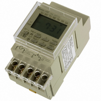
H5F-KB
Description
TIMER DAILY DGTL PRESET DIN MNT
Manufacturer
Omron
Series
H5Fr
Specifications of H5F-KB
Timing Range
24 Hrs x 7 Days
Supply Voltage
100 V to 240 V
Display Type
LCD Backlight
Termination Style
Screw
Time Range
24hr X 7day
Power Consumption
2.4VA
Reset Time
1min
Lead Free Status / RoHS Status
Lead free / RoHS Compliant
Lead Free Status / RoHS Status
Lead free / RoHS Compliant, Lead free / RoHS Compliant
Other names
Z2440
Available stocks
Company
Part Number
Manufacturer
Quantity
Price
Company:

Part Number:
H5F-KB
Manufacturer:
INFINEON
Quantity:
21 600


Precautions
Refer to Safety Precautions for All Timers.
Do not touch any of the terminals while power is being supplied. Doing
so may result in electric shock. Be sure to mount the terminal cover
after wiring.
Do not use the Time Switch in locations subject to flammable or
explosive gases. Doing so may result in explosion.
Do not disassemble, repair, or modify the Time Switch. Doing so may
result in electric shock, fire, or malfunction.
Tighten terminal screws to the specified torque (approx. 0.98 N⋅m).
Loose screws may occasionally cause fires or malfunction. (Maximum
torque: 1.17 N⋅m)
Before changing times or other settings while power is being supplied,
either turn OFF the power on the load side or set the output ON/OFF
switch to OFF and confirm the safety of the system.
The life expectancy of the output relays depends on the switching
capacity and switching conditions. Consider the actual application
conditions and use the Time Switch within the rated load and
electrical service life. If using the Time Switch beyond its ratings is
unavoidable, use it together with an electromagnetic switch or
contactor as shown in the following diagram.
Using the Time Switch beyond its life expectancy may result in contact
deposition or burning.
Do not disassemble the Time Switch, deform the Time Switch by
applying pressure, heat the Time Switch to temperatures above
100°C, or incinerate the Time Switch. Doing any of these may cause
the built-in lithium battery to ignite or rupture.
■ Wiring
• Be sure to wire the terminals correctly.
• Do not connect more than two crimp terminals to each Time Switch
• Perform wiring using appropriate wires of the type specified in this
■ Power Supplies
• Make sure that the fluctuation of the supply voltage is within the
• Make sure that the voltage applied is within the specified range,
• Apply the power supply voltage through a breaker, relay or switch in
• When the power is turned ON, an inrush current will flow for a short
terminal. Faulty contact may result in burn injury or fire.
document. Using a different type of wire may result in burn injury or
fire due to abnormal heat generation.
permissible range.
otherwise the internal elements of the Time Switch may be dam-
aged.
such a way that the voltage reaches a fixed value immediately, oth-
erwise they may not be reset or a Time Switch error may result.
time (approx. 2 A for 0.3 ms at 264 VAC). Depending on the power
supply capacity, operation may not start. Be sure to use a power
supply with a sufficient capacity and a breaker.
Electromagnetic
contactor or
electromagnetic
switch
Crossover
!CAUTION
Power supply
Load
Power supply
Circuit
H5F
■ Operating Environment
• Do not use the Time Switch in locations where condensation may
• Do not leave the Time Switch for long periods (i.e., one month or
• Separate the Time Switch from any potential sources of noise, such
• Separate the Time Switch from the source of static electricity when
• Use the Time Switch within the ratings specified for temperature
• Do not use the Time Switch in environments subject to shocks or
• Do not use the Time Switch in locations subject to dust, corrosive
• Store at the specified temperature. If the H5F has been stored at a
• This Time Switch is not waterproof or oil-proof. Do not use it in
• Organic solvents (such as paint thinner), as well as very acidic or
■ Installation
• Mounting the Time Switches side-by-side may reduce the life
• When using heaters, be sure to use a thermal switch for the load
• When driving an inductive load (e.g., coil), a surge voltage is gener-
As a rough guide, the capacitor (C) and resistor (R) should have the
following specifications:
C: 0.5 to 1 µF for a switching current of 1 A
R: 0.5 to 1 Ω for a switching voltage of 1 V
Use a capacitor with a dielectric strength appropriate for the power
supply voltage. Use an AC-type capacitor with AC circuits. There
may be cases where, due to inconsistencies in the nature and char-
acteristics of the load, delays in restoring the load may cause prob-
lems. Be sure to confirm that correct operation is possible under the
actual operating conditions.
occur due to high humidity or where temperature changes are
severe.
longer) at a high temperature with output current in the ON state.
Doing so may result in the premature deterioration of internal com-
ponents (e.g., electrolytic capacitors).
as high-voltage lines. When using inductive loads (e.g., electro-
magnetic relays), connect noise-absorbing elements (resistor and
capacitor) to both ends of the coil.
using the Time Switch in an environment where a large amount of
static electricity is produced (e.g., forming compounds, powders, or
fluid materials being transported by pipe).
and humidity.
vibration beyond the ranges specified in this document.
gases, or direct sunlight.
temperature of less than −10°C, allow the H5F to stand at room
temperature for at least 3 hours before use.
locations where water or oil may enter the Time Switch interior.
basic solutions might damage the outer casing of the H5F.
expectancies of internal components.
circuit.
ated when the contacts (i.e., Time Switch output) are switched, and
in some cases this may damage other devices connected to the
Time Switch or the same line. Absorb the surge with a capacitor
and resistor as shown in the following diagram.
Power supply
Time Switch output
C
R
Inductive
load
H5F
8
Related parts for H5F-KB
Image
Part Number
Description
Manufacturer
Datasheet
Request
R

Part Number:
Description:
TIMER DIGITAL DAILY 100-240VAC
Manufacturer:
Omron
Datasheet:


Part Number:
Description:
G6S-2GLow Signal Relay
Manufacturer:
Omron Corporation
Datasheet:
Part Number:
Description:
Compact, Low-cost, SSR Switching 5 to 20 A
Manufacturer:
Omron Corporation
Datasheet:
Part Number:
Description:
Manufacturer:
Omron Corporation
Datasheet:
Part Number:
Description:
Manufacturer:
Omron Corporation
Datasheet:
Part Number:
Description:
Manufacturer:
Omron Corporation
Datasheet:
Part Number:
Description:
Manufacturer:
Omron Corporation
Datasheet:
Part Number:
Description:
Manufacturer:
Omron Corporation
Datasheet: