LT4H-AC240V Panasonic Electric Works, LT4H-AC240V Datasheet - Page 20
LT4H-AC240V
Manufacturer Part Number
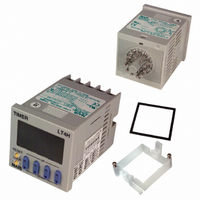
LT4H-AC240V
Description
TIMER RELAY DIGITAL 240VAC 11PIN
Manufacturer
Panasonic Electric Works
Series
LT4Hr
Type
Digital Timerr
Specifications of LT4H-AC240V
Contact Form
SPDT
Dimensions
48mmW×48mmH×75.6mmD
Enclosure Rating
IP66
Ip Rating
IP66
Memory
EEPROM
Mounting Type
DIN Rail/Flush
Output Type
Relay
Primary Type
Controller
Special Features
EEPROM
Termination
Plug-In
Voltage, Supply
100 to 240 VAC
Lead Free Status / RoHS Status
Lead free / RoHS Compliant
Other names
255-1214
Available stocks
Company
Part Number
Manufacturer
Quantity
Price
Company:

Part Number:
LT4H-AC240V
Manufacturer:
Panasonic Electric Works
Quantity:
135
Company:
Part Number:
LT4H-AC240VS
Manufacturer:
Panasonic Electric Works
Quantity:
135


INSTALLING DIN SIZE TIMER
Installations
1. Surface mount
1) For the timers of PM4H and LT4H
series, use the pin type timer. With the
PM4S and QM4H series, only pin-type
timers are available.
56
2) Put the terminal socket on the board
directly or put it on the DIN rail (Fig. 1).
3) Insert the timer into the terminal sock-
et and fix it with clip (Fig. 2)
4) On DIN rail mounting, mount the timer
on the DIN rail tightly to get the proper
dimension (Fig. 3).
Terminal socket
5) 8-pin type should be connected with
terminal socket (AT8-DF8K). 11-pin type
should be connected with terminal sock-
et (AT8-DF11K).
6) DIN rail (AT8-DLA1) is also available
(1 m).
2. Flush mount
1) For the timers of PM4H and LT4H
series, it is recommended to use the
built-in screw terminal type for flush
mount. (Mounting frame and rubber
gasket are provided when timer is
shipped.)
If the pin type is used, the mounting
frame (AT8-DA4) and rubber gasket
(ATC18002 for surface waterproofing)
that are available at extra costs are nec-
essary. If the pin connection socket is
the 8-pin type, use the 8P cap (AD8-
RC); or if it is the 11-pin type, use the
11P cap (AT8-DP11).
( Fig. 3 )
DIN rail
( Fig. 1 )
( Fig. 2 )
2) How to mount the timer
From the panel front, pass the timer
through the square hole. Fit the mount-
ing frame from the rear, and then push it
in so that the clearance between the
mounting frame and the panel surface is
minimized. In addition, lock the mount-
ing frame with a screw.
• Screw terminal type
• Pin type
3) Caution in mounting the timer
• PM4H, and LT4H series
used as the waterproof types, tighten the
reinforcing screws on the mounting
frames so that the timers, the rubber
gaskets, and the panel surfaces are
tightly contacted with each other.
(Tighten the two screws with uniform
force and make sure that there is no rat-
tling. If the screws are tightened too
excessively, the mounting frame may
come off.)
cover and the rubber gasket removed,
the waterproofing characteristic is lost.
4) Installation
Loosen the screws on the mounting
frame, spread the edge of frame and
remove it.
Pull the mounting
frame backward while
spreading out its hooks
with your thumbs and
index fingers.
a If the PM4H and the LT4H series are
b If the timer is installed with the panel
Rubber gasket
Panel cover
Panel
Mounting frame
Screw
Screw
Push in
Push in
1
1
2
8) Although the
timers can be
mounted adjacent
to each other in
this case, it is rec-
ommended to
arrange the
mounting holes
as shown in the
right figure to
facilitate attaching
and detaching the
mounting frame.
9) Adjacent
mounting
Although the
timers can be
mounted adjacent to each other, remem-
ber that the panel surface of PM4H or
LT4H series timer will lose its water-
resistant effect. (Panel thickness: 1 to 5
mm
A = (48 × n – 2.5)
When lining up the
timers horizontally,
set the frames in
such a position so
the formed spring
areas are at the
top and bottom.
When lining up the
timers vertically,
set the frames in
such a position as
the formed spring
areas are at the
right and left.
5) Correctly connect the pins while see-
ing the pin connection diagram.
Tighten the terminal screws with a torque
of 0.8 N·cm or less. The screws are
M3.5. (screw-tightened terminal type)
6) If the pin type is used, the rear termi-
nal block (ATC78041) or the 8P cap
(AD8-RC) is necessary to connect the
pins. For the 11-pin type, use the rear
terminal block (ATC78051) or the 11P
cap (AT8-DP11) and avoid directly sol-
dering the round pins on the timer.
7) Panel cutout dimensions
1.772
45
+
+
0.6
0
.024
0
.039 to .197
1.772
45
+
+
0.6
0
.024
0
inch)
The standard panel
cutout dimensions are
shown in the left figure.
(Panel thickness: 1 to 5
mm
+0.6
+0
1.772
1.772
80 mm
3.150 inch
or more
Formed spring
Formed spring
45
45
.039 to .197
(mm)
+
+
0.6
0
.024
0
+
+
1.772
0.6
0
.024
0
45
+
+
0.6
0
.024
0
80 mm
3.150 inch
or more
A
inch)
Related parts for LT4H-AC240V
Image
Part Number
Description
Manufacturer
Datasheet
Request
R

Part Number:
Description:
TIMER RELAY DIG 24VDC SCREW TERM
Manufacturer:
Panasonic Electric Works
Datasheet:
Part Number:
Description:
TIMER RELAY DIGITAL 240VAC SCREW
Manufacturer:
Panasonic Electric Works
Datasheet:

Part Number:
Description:
TIMER RELAY DIG 24VDC OCT 11PIN
Manufacturer:
Panasonic Electric Works
Datasheet:

Part Number:
Description:
Timer Multifunction
Manufacturer:
NAIS
Datasheet:

Part Number:
Description:
TIMER DIGITAL 24VDC SCREW TERM
Manufacturer:
Panasonic Electric Works
Datasheet:
Part Number:
Description:
Manufacturer:
Panasonic Electric Works
Datasheet:
Part Number:
Description:
Manufacturer:
Panasonic Electric Works
Datasheet:

Part Number:
Description:
CONN SOCKET P4 .4MM 50POS SMD
Manufacturer:
Panasonic Electric Works
Datasheet:
Part Number:
Description:
CONN SOCKET .8MM 16POS SMD
Manufacturer:
Panasonic Electric Works
Datasheet:
Part Number:
Description:
CONN HEADER .8MM 16POS SMD
Manufacturer:
Panasonic Electric Works
Datasheet:
Part Number:
Description:
CONN SOCKET .8MM 20POS SMD
Manufacturer:
Panasonic Electric Works
Datasheet:
Part Number:
Description:
CONN SOCKET .8MM 20POS SMD
Manufacturer:
Panasonic Electric Works
Datasheet:
Part Number:
Description:
CONN HEADER .8MM 20POS SMD
Manufacturer:
Panasonic Electric Works
Datasheet:
Part Number:
Description:
CONN SOCKET .8MM 22POS SMD
Manufacturer:
Panasonic Electric Works
Datasheet:
Part Number:
Description:
CONN SOCKET .8MM 30POS SMD
Manufacturer:
Panasonic Electric Works
Datasheet: