LT4H-AC240V Panasonic Electric Works, LT4H-AC240V Datasheet - Page 6
LT4H-AC240V
Manufacturer Part Number
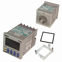
LT4H-AC240V
Description
TIMER RELAY DIGITAL 240VAC 11PIN
Manufacturer
Panasonic Electric Works
Series
LT4Hr
Type
Digital Timerr
Specifications of LT4H-AC240V
Contact Form
SPDT
Dimensions
48mmW×48mmH×75.6mmD
Enclosure Rating
IP66
Ip Rating
IP66
Memory
EEPROM
Mounting Type
DIN Rail/Flush
Output Type
Relay
Primary Type
Controller
Special Features
EEPROM
Termination
Plug-In
Voltage, Supply
100 to 240 VAC
Lead Free Status / RoHS Status
Lead free / RoHS Compliant
Other names
255-1214
Available stocks
Company
Part Number
Manufacturer
Quantity
Price
Company:

Part Number:
LT4H-AC240V
Manufacturer:
Panasonic Electric Works
Quantity:
135
Company:
Part Number:
LT4H-AC240VS
Manufacturer:
Panasonic Electric Works
Quantity:
135


LT4H/-L
Setting the operation mode, time range, and time
Setting procedure 1) Setting the operation mode and time range
Setting procedure 2) Setting the time
• Changing the set time
1. It is possible to change the set time
with the up and down keys even dur-
ing time delay with the timer.
However, be aware of the following
points.
1) If the set time is changed to less than
the elapsed time with the time delay set
to the addition direction, time delay will
continue until the elapsed time reaches
full scale, returns to zero, and then
reaches the new set time. If the set time
• Power failure memory
The EEPROM is used for power failure memory. It has a life of Min. 10
The EEPROM is overwriting with the following timing.
* Be aware that the contents of EEPROM for all modes will be overwritten when power is turned OFF during input to external lock terminals R to E and
38
Such an action does not exist by doing lock operation from the front.
Output mode
Power ON delay (2) A2
Addition G
Other modes
Set the operation mode and time range with the DIP switches on the side of the LT4H timer.
DIP switches
* The 8-pin type does not have the stop input, so that the dip
Set the set time with the keys (UP and DOWN keys) on the front of the LT4H timer.
Q Elapsed time display
W Set time display
E Time delay indicator
R Controlled output indicator
T Reset indicator
Y Lock indicator
U Time units display
Front display section
switch can be changed over between reset and start inputs.
The signal range of the lock input is fixed (minimum 20 ms).
*4
1
2
3
5
6
7
8
Minimum input reset, start, and
Time delay direction
(Same for screw terminal type)
stop signal width
Operation mode
Time range
Overwrite timing
When power is OFF
Change of preset value or start, reset input
When power is OFF after being ON
When power is OFF after changing preset value
1
2
Item
3
4
5
6
7
8
DIP switches
is changed to a time above the elapsed
time, the time delay will continue until the
elapsed time reaches the new set time.
2) If the time delay is set to the subtrac-
tion direction, time delay will continue
until “0” regardless of the new set time.
2. If the set time is changed to “0,” the
unit will operate differently depending
on the operation mode.
1) If the operation mode is set to A
(power on delay 1) or A2 (power on
Addition Subtraction
20 ms
OFF
Refer to table 1
Refer to table 2
10
11
3
4
5
6
DIP switch
1 ms
ON
LT4H
RESET
LOCK
O P .
R S T
L O C K
h
DOWN
UP
m
Table 1: Setting the operation mode
Table 2: Setting the time range
Notes: 1) Set the DIP switches before installing the timer.
s
TIMER
5
OFF
OFF
OFF
OFF
OFF
OFF
OFF
OFF
ON
ON
ON
ON
ON
ON
ON
ON
over-writings.
1
6
DIP switch No.
DIP switch No.
2) When the DIP SW setting is changed, turn off the power once.
3) The DIP switches are set as ON before shipping.
OFF
OFF
OFF
OFF
OFF
OFF
OFF
OFF
ON
ON
ON
ON
ON
ON
ON
ON
2
7
1
2
7
8
9
OFF
OFF
OFF
OFF
OFF
OFF
OFF
OFF
ON
ON
ON
ON
ON
ON
ON
ON
delay 2), the output will turn on when the
power supply is turned on. However, the
output will be off while reset is being
input.
2) In the other modes, the output turns
on when the start is input. When the
operation mode is C (signal off delay), D
(Pulse one shot), or F (Signal flicker),
only when the start input is on does the
output turn on. Also, when the reset is
being input, the output is off.
3
8
I UP keys
O DOWN keys
P RESET switch
{ LOCK switch
Changes the corresponding digit of the
set time in the addition direction
(upwards)
Changes the corresponding digit of the
set time in the subtraction direction
(downwards)
Resets the elapsed time and the output
Locks the operation of all keys on the unit
A: Power on delay 1
A2: Power on delay 2
B: Signal on delay
C: Signal off delay
D: Pulse One shot
E: Pulse On delay
F: Signal Flicker
G: Totalizing On delay
0.001 s to 9.999 s
0.01 s to 99.99 s
0.1 s to 999.9 s
1 s to 9999 s
0 min 01 s to 99 min 59 s
0.1 min to 999.9 min
0 h 01 min to 99 h 59 min
0.1 h to 999.9 h
Operation mode
Time range
7
to
6
.
Related parts for LT4H-AC240V
Image
Part Number
Description
Manufacturer
Datasheet
Request
R

Part Number:
Description:
TIMER RELAY DIG 24VDC SCREW TERM
Manufacturer:
Panasonic Electric Works
Datasheet:
Part Number:
Description:
TIMER RELAY DIGITAL 240VAC SCREW
Manufacturer:
Panasonic Electric Works
Datasheet:

Part Number:
Description:
TIMER RELAY DIG 24VDC OCT 11PIN
Manufacturer:
Panasonic Electric Works
Datasheet:

Part Number:
Description:
Timer Multifunction
Manufacturer:
NAIS
Datasheet:

Part Number:
Description:
TIMER DIGITAL 24VDC SCREW TERM
Manufacturer:
Panasonic Electric Works
Datasheet:
Part Number:
Description:
Manufacturer:
Panasonic Electric Works
Datasheet:
Part Number:
Description:
Manufacturer:
Panasonic Electric Works
Datasheet:

Part Number:
Description:
CONN SOCKET P4 .4MM 50POS SMD
Manufacturer:
Panasonic Electric Works
Datasheet:
Part Number:
Description:
CONN SOCKET .8MM 16POS SMD
Manufacturer:
Panasonic Electric Works
Datasheet:
Part Number:
Description:
CONN HEADER .8MM 16POS SMD
Manufacturer:
Panasonic Electric Works
Datasheet:
Part Number:
Description:
CONN SOCKET .8MM 20POS SMD
Manufacturer:
Panasonic Electric Works
Datasheet:
Part Number:
Description:
CONN SOCKET .8MM 20POS SMD
Manufacturer:
Panasonic Electric Works
Datasheet:
Part Number:
Description:
CONN HEADER .8MM 20POS SMD
Manufacturer:
Panasonic Electric Works
Datasheet:
Part Number:
Description:
CONN SOCKET .8MM 22POS SMD
Manufacturer:
Panasonic Electric Works
Datasheet:
Part Number:
Description:
CONN SOCKET .8MM 30POS SMD
Manufacturer:
Panasonic Electric Works
Datasheet: