PM5S-A-24-240V Panasonic Electric Works, PM5S-A-24-240V Datasheet
PM5S-A-24-240V
Specifications of PM5S-A-24-240V
Available stocks


Related parts for PM5S-A-24-240V


PM5S-A-24-240V Summary of contents
Page 1
Timers/Time Switches/Counters/Hour Meters Timers/Time Switches/Counters/Hour Meters ARCT1B274E ’06.10 ’06–’07 Matsushita Electric Works, Ltd. ...
Page 2
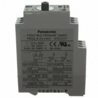
... PM5S-A/S/M PM5S-A PM5S-S PM5S-M Protective Rated operating voltage PM5S-A-24-240V IP40 24 to 240V AC/DC PM5S-S-24-240V PM5S-M-24-240V PM5S-A/PM5S-S/PM5S-M All types of PM5S timer have multi-time range. 16 time ranges are selectable 500h (Max. range) is controlled. Part number ...
Page 3
... Between contacts of same pole 55°C 131° 55Hz: 1 cycle/min Single amplitude of 0.35mm (10min on 3 axes 55Hz: 1 cycle/min Single amplitude of 0.75mm ( axes) PM5S-S • Timed-out 2 Form C Contact PM5S 240V AC/DC 50/60Hz common 2.6 VA (AC), 1.4 W (DC) 5A 250V AC (resistive load) Pulse ON-delay Pulse Flicker Pulse ON-flicker ...
Page 4
... L S Sec can be selected by the operation mode selector switch. In the next pages the different modes will PM5S be explained 75.0 2.953 22.5 .886 75.0 2.953 9.0 .354 .197 48.0 1.890 PM5S MULTIRANGE TIMER 41.3 PM5S-A-24-240V 1.626 20 .787 37.5 1.476 PM5S-A/S/M 5.0 mm inch 75 ...
Page 5
... PM5S-A/S/M Operation mode PM5S-A/M Operation type Turn the operation selector to Timing operation starts when terminals A1 – B1 are connected while power is on. Control output is turned on after the set time regardless of duration of operation signal ON-delay ON Turn the operation selector to Timing operation starts when terminals A1 – B1 are connected while power is on ...
Page 6
... When power is applied continuously, the time cycle begins. The out- put contacts change state after the time delay is completed. Power ON-delay Modes and time setting 1) Operation mode setting [PM5S-A] 6 operation modes are selectable with operation mode selector. Turn the operation mode selector with screw driver ...
Page 7
... Start A 2 Operates with relay ON When dismounting the PM5S pull out portion (C) with a flat- blade screwdriver and remove the Timer from the mounting track. must be more than the rated 2 must be less than the rated 2 2) Since the body cover is consisted of polycarbonate resin, prevent from con- ...
Page 8
... Correct supply A2 Short-circuit current A1 B1 PM5S A2 Fig. B The PM5S series is provided with a transformer less power supply system. 2. External surge protection may be required if the following values are exceeded. Otherwise, the internal circuit will be damaged. Operating voltage 24 to 240 V AC Surge voltage 4,000 V Surge wave form [± ...
Page 9
DIN SIZE TIMERS COMMON OPTIONS Terminal sockets (Unit: mm Type Appearance • DIN rail socket (8-pin) PM4H-S PM4H-M PM4H-SD PM4H-F8 PM4H-F8R 24 .945 PM4H-W LT4H LT4H-L 70 2.756 50 LT4H-W 1.969 QM4H PM4S (8-pin type) ATC180031 • DIN rail socket ...
Page 10
MOUNTING PARTS • Rubber gasket 50.0 1.969 1.0 50.0 .039 1.969 ATC18002 The rubber gasket is enclosed in the PM4H (screw terminal type) and the LT4H series. • Mounting rails (Applicable for 5.5 DIN and IEC standards) .217 AT8-DLA1 Length: ...
Page 11
INSTALLING DIN SIZE TIMER Installations 1. Surface mount 1) For the timers of PM4H and LT4H series, use the pin type timer. With the PM4S and QM4H series, only pin-type timers are available. 2) Put the terminal socket on the ...