543382-7 Tyco Electronics, 543382-7 Datasheet - Page 3
543382-7
Manufacturer Part Number
543382-7
Description
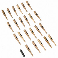
INSERT/EXTRACT TIP 25-KIT
Manufacturer
Tyco Electronics
Series
AMPLIMITE®r
Type
Insertion / Extraction Toolsr
Specifications of 543382-7
Tool Type
Insertion/Extraction Tool Tip
Product
Insertion Tool
For Use With
Posted HD20 Contacts
Lead Free Status / RoHS Status
Not applicable / Not applicable
For Use With/related Products
D-Sub Terminals
Lead Free Status / Rohs Status
Lead free / RoHS Compliant


4.2. Extracting A Wire Crimped Contact
Rev B
Slide Extraction Tip Over
Contact Post or Crimp
Barrel
2. Slide thumb over the wire toward the end of the
tip.
3. Slide tip over contact wire barrel until the tip butts
against the contact shoulder.
4. Align contact with the BACK of the contact cavity.
Push contact straight into the contact cavity until the
contact bottoms.
5. Remove the insertion tool; then pull back on the
wire to ensure that the contact is locked into the
contact cavity.
1. Position tool handle between thumb and
fingertips, and align contact wire with the wire slot
on the tip. Hold wire in this position with your thumb.
2. Slide your thumb over the wire toward the end of
the insertion tip.
NOTE
i
The wire must be positioned inside the wire slot of
the tip.
Wire
Slot
(Figure 4)
Back of Receptacle
Connector 205439-1 (Ref)
Figure 4
Extraction Handle
4.3. Inserting A Posted Contact
3. Place tip over the contact post or crimp barrel and
slide the tip straight into the contact cavity until the
tip bottoms against the contact shoulder.
4. Holding the wire tight against the tool handle, pull
back on the tool handle to extract the contact. If you
experience difficulty in extracting the contact, repeat
Steps 1 through 4.
1. Place the contact in the contact cavity. Do NOT
push on the contact post.
2. Position the tip over the contact post. Move the
tool along the post until the tip butts against the
contact stabilizer. Align the tip on the stabilizer as
shown in Figure 5.
3. Hold the tool handle, and push the contact post to
make certain that the contact is locked in the cavity.
NOTE
NOTE
i
i
The wire must be positioned inside the wire slot of
the tip.
Contacts with tail lengths longer than 10.85 mm
[.427 in.] must use yellow color coded insertion tips
(Figure 5)
Wire
408-9404
3 of 6