1643914-1 Tyco Electronics, 1643914-1 Datasheet - Page 7
1643914-1
Manufacturer Part Number
1643914-1
Description
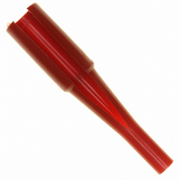
TOOL INSERTION/REMOVAL SIZE #8
Manufacturer
Tyco Electronics
Series
ELCONr
Type
Extraction Toolr
Specifications of 1643914-1
Tool Type
Insertion/Extraction Tool
Description/function
Red tool
Wire Gauge Range
8
Product
Insertion / Extraction Tool
For Use With/related Products
Circular Connector Contacts
For Use With
A36295 - CONN SOCKET #8 PCBA36294 - CONN SOCKET #8 CRIMP REMOVABLEA36280 - CONN PIN #8 PCB SILVERA36279 - CONN PIN #8 CRIMP SILVER
Lead Free Status / RoHS Status
Not applicable / Not applicable
Other names
A36311


Panel Thickness: 4.76 mm [.188 in.] (Max)
Rev D
QUADPOWER
DUALPOWER
TOP DRAWER, DOUBLE DRAWER
125A MIDDLE DRAWER
75A MIDDLE DRAWER
LOWER DRAWER
MINI DRAWER
CAUTION
CAUTION
NOTE
B. PC Board Tolerance
Maximum allowable bow of the pc board shall be 0.03 mm [.001 in.] over the length of the connector.
C. Connector Placement
The connector number one position must be aligned with the number one position board hole. When
placing connectors on the pc board, make sure that the contact solder tails are aligned and started into the
matching holes before seating the connector onto the pc board.
i
!
!
CONNECTOR
Contact the Product Information Center at the number listed at the bottom of page 1 for suitability of other board
materials and thicknesses.
Connectors should be handled only by the housing to avoid deformation, contamination, or damage to the contact
solder tails.
For applications using panel mounted threaded fasteners, care must be taken that the threaded hole does not
compromise the shoulder area of the shoulder screw used to fasten the float mount connector.
Threaded Hole for Applicable
Shoulder Screw (2 Places)
53.98 [2.125]
35.56 [1.400]
98.29 [3.870]
72.01 [2.835]
76.20 [3.000]
76.20 [3.000]
69.75 [2.746]
A
A
B
Recommended Panel Cutout
Tyco Electronics Corporation
43.18 [1.700]
25.40 [1.000]
88.90 [3.500]
62.99 [2.480]
67.31 [2.650]
66.67 [2.625]
58.55 [2.305]
Figure 7
B
C
E
43.18 [1.700]
43.18 [1.700]
43.18 [1.700]
35.56 [1.400]
36.83 [1.450]
25.40 [1.000]
23.62 [.930]
6.35 mm [.250 in.]
Mounting Hole Dia
(4 Places)
C
D
50.80 [2.000]
33.02 [1.300]
95.25 [3.750]
------
------
------
------
D
24.89 [.980]
24.89 [.980]
24.89 [.980]
------
------
------
------
E
7 of 17