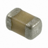
0402ZD104KAT2A AVX Corporation, 0402ZD104KAT2A Datasheet - Page 11

0402ZD104KAT2A
Manufacturer Part Number
0402ZD104KAT2A
Description
CAP CERM .1UF 10% 10V X5R 0402
Manufacturer
AVX Corporation
Series
0402r
Datasheets
1.0603ZD105KAT2A.pdf
(3 pages)
2.0402ZD104KAT2A.pdf
(3 pages)
3.0402ZD104KAT2A.pdf
(18 pages)
Specifications of 0402ZD104KAT2A
Capacitance
0.1µF
Package / Case
0402 (1005 Metric)
Voltage - Rated
10V
Tolerance
±10%
Temperature Coefficient
X5R
Mounting Type
Surface Mount, MLCC
Operating Temperature
-55°C ~ 85°C
Applications
General Purpose
Size / Dimension
0.039" L x 0.020" W (1.00mm x 0.50mm)
Thickness
0.56mm Max
Tolerance (+ Or -)
10%
Voltage
10VDC
Temp Coeff (dielectric)
X5R
Operating Temp Range
-55C to 85C
Mounting Style
Surface Mount
Construction
SMT Chip
Case Style
Ceramic Chip
Failure Rate
Not Required
Wire Form
Not Required
Product Length (mm)
1mm
Product Depth (mm)
0.5mm
Product Height (mm)
0.56mm
Product Diameter (mm)
Not Requiredmm
Dielectric Characteristic
X5R
Capacitance Tolerance
± 10%
Voltage Rating
10VDC
Capacitor Case Style
0402
No. Of Pins
2
Capacitor Mounting
SMD
Rohs Compliant
Yes
Case Size
0402
Dielectric Strength
No breakdown or visual defects
Dissipation Factor
5 %
Dissipation Factor, Test Condition
(Max.)
Insulation Resistance
100000 Megohms
Length
0.040 in. ±0.004 in.
Material, Element
Ceramic
Package Type
7 in. Reel
Temperature, Operating, Maximum
+125 °C
Temperature, Operating, Minimum
-55 °C
Termination
SMT
Voltage, Rating
10 VDC
Width
0.020 in. ±0.004 in.
Operating Temperature Range
- 55 C to + 85 C
Temperature Coefficient / Code
X5R
Product
General Type MLCCs
Dimensions
0.5 mm W x 1 mm L x 0.56 mm H
Dissipation Factor Df
5
Termination Style
SMD/SMT
Lead Free Status / RoHS Status
Lead free / RoHS Compliant
Features
-
Ratings
-
Lead Spacing
-
Lead Free Status / Rohs Status
RoHS Compliant part
Other names
478-1129-2
General Description
Table 1: EIA and MIL Temperature Stable and General
In specifying capacitance change with temperature for Class
2 materials, EIA expresses the capacitance change over an
operating temperature range by a 3 symbol code. The first
symbol represents the cold temperature end of the temper-
ature range, the second represents the upper limit of the
operating temperature range and the third symbol repre-
sents the capacitance change allowed over the
operating temperature range. Table 1 provides a detailed
explanation of the EIA system.
66
Percent Capacity Change Over Temperature Range
EXAMPLE – A capacitor is desired with the capacitance value at 25°C
to increase no more than 7.5% or decrease no more than 7.5% from
-30°C to +85°C. EIA Code will be Y5F.
Temperature characteristic is specified by combining range and
change symbols, for example BR or AW. Specification slash sheets
indicate the characteristic applicable to a given style of capacitor.
Symbol
Symbol
RS198
C
Code
A
B
W
R
S
X
Y
Z
X7
X6
X5
Y5
Z5
Application Codes
U
D
E
P
R
S
V
F
T
Cap. Change
+15%, -15%
+22%, -22%
+22%, -56%
+15%, -15%
+30%, -70%
+20%, -20%
Zero Volts
Temperature Range
MIL CODE
EIA CODE
Percent Capacity Change
-55°C to +85°C
-55°C to +125°C
-55°C to +150°C
Temperature Range
+10°C to +85°C
-55°C to +125°C
-55°C to +105°C
-55°C to +85°C
-30°C to +85°C
+22%, - 56%
+22%, -33%
+22%, -82%
±3.3%
±4.7%
±7.5%
±10%
±15%
±22%
Cap. Change
+15%, -40%
+22%, -56%
+22%, -66%
+15%, -25%
+30%, -80%
+20%, -30%
Rated Volts
Effects of Voltage – Variations in voltage have little effect
on Class 1 dielectric but does affect the capacitance and
dissipation factor of Class 2 dielectrics. The application of
DC voltage reduces both the capacitance and dissipation
factor while the application of an AC voltage within a
reasonable range tends to increase both capacitance and
dissipation factor readings. If a high enough AC voltage is
applied, eventually it will reduce capacitance just as a DC
voltage will. Figure 2 shows the effects of AC voltage.
Capacitor specifications specify the AC voltage at which to
measure (normally 0.5 or 1 VAC) and application of the
wrong voltage can cause spurious readings. Figure 3 gives
the voltage coefficient of dissipation factor for various AC
voltages at 1 kilohertz. Applications of different frequencies
will affect the percentage changes versus voltages.
Typical effect of the application of DC voltage is shown in
Figure 4. The voltage coefficient is more pronounced for
higher K dielectrics. These figures are shown for room tem-
perature conditions. The combination characteristic known
as voltage temperature limits which shows the effects of
rated voltage over the operating temperature range is
shown in Figure 5 for the military BX characteristic.
10.0
50
40
30
20
10
6.0
8.0
4.0
2.0
0
0
Curve 1 - 100 VDC Rated Capacitor
Curve 2 - 50 VDC Rated Capacitor
Curve 3 - 25 VDC Rated Capacitor
D.F. vs. A.C. Measurement Volts
Cap. Change vs. A.C. Volts
.5
AC Measurement Volts at 1.0 KHz
12.5
Volts AC at 1.0 KHz
1.0
Figure 2
Figure 3
X7R
X7R
25
1.5
2.0
37.5
2.5
Curve 3
Curve 1
Curve 2
50


