RDER72J104K8K1C11B Murata Electronics North America, RDER72J104K8K1C11B Datasheet - Page 15
RDER72J104K8K1C11B
Manufacturer Part Number
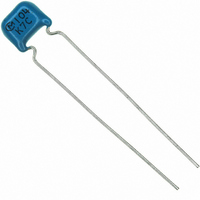
RDER72J104K8K1C11B
Description
CAP CER 100000PF 630V X7R RADIAL
Manufacturer
Murata Electronics North America
Series
RDEr
Datasheets
1.RPEF51H104Z2K1A03B.pdf
(2 pages)
2.RDEE41H104M0K1C03B.pdf
(3 pages)
3.RDER72J682K2K1C11B.pdf
(39 pages)
4.RDER72J104K8K1C11B.pdf
(1 pages)
Specifications of RDER72J104K8K1C11B
Capacitance
0.1µF
Voltage - Rated
630V
Tolerance
±10%
Temperature Coefficient
X7R
Mounting Type
Through Hole
Operating Temperature
-55°C ~ 125°C
Features
High Voltage
Applications
General Purpose
Package / Case
Radial
Size / Dimension
0.217" L x 0.295" W (5.50mm x 7.50mm)
Thickness
4.00mm Max
Lead Spacing
0.197" (5.00mm)
Lead Style
Flat Bent
Lead Free Status / RoHS Status
Lead free / RoHS Compliant
Ratings
-
Other names
490-4821
Available stocks
Company
Part Number
Manufacturer
Quantity
Price
Company:

Part Number:
RDER72J104K8K1C11B
Manufacturer:
PANASONIC
Quantity:
30 000


!Note
• This PDF catalog is downloaded from the website of Murata Manufacturing co., ltd. Therefore, it’s specifications are subject to change or our products in it may be discontinued without advance notice. Please check with our
• This PDF catalog has only typical specifications because there is no space for detailed specifications. Therefore, please approve our product specifications or transact the approval sheet for product specifications before ordering.
sales representatives or product engineers before ordering.
!Note
Table A
*1: Nominal values denote the temperature coefficient within a range of
No.
Char.
15
18
16
17
C0G
25 to 125˚C
Continued from the preceding page.
Humidity
(Steady
State)
Humidity
Load
High
Temperature
Load
Solvent
Resistance
• Please read rating and !CAUTION (for storage, operating, rating, soldering, mounting and handling) in this catalog to prevent smoking and/or burning, etc.
• This catalog has only typical specifications because there is no space for detailed specifications. Therefore, please approve our product specifications or transact the approval sheet for product specifications before ordering.
Nominal Values
(ppm/˚C) *1
0T30
Item
Appearance No defects or abnormalities
Capacitance
Change
Q/D.F.
Insulation
Resistance
Appearance No defects or abnormalities
Capacitance
Change
Q/D.F.
Insulation
Resistance
Appearance
Capacitance
Change
Q/D.F.
Insulation
Resistance
Appearance No defects or abnormalities
Marking
Max.
0.58
-55˚C
Capacitance Change from 25˚C (%)
-0.24
Min.
Temperature Compensating Type High Dielectric Constant Type
Within T5% or T0.5pF
(whichever is larger)
30pF min. : Q U 350
10pF to 30pF : Q U 275+5C/2
10pF max. : Q U 200+10C
C : Nominal capacitance (pF)
1,000MΩ or 50MΩ • µF min.
(whichever is smaller)
Within T7.5% or T0.75pF
(whichever is larger)
30pF min. : Q U 200
30pF max. : Q U 100+10C/3
C : Nominal capacitance (pF)
500MΩ or 25MΩ • µF min.
(whichever is smaller)
No defects or abnormalities
Within T3% or T0.3pF
(whichever is larger)
30pF min. : Q U 350
10pF to 30pF : Q U 275+5C/2
10pF max. : Q U 200+10C
C : Nominal capacitance (pF)
1,000MΩ or 50MΩ • µF min.
(whichever is smaller)
Legible
Max.
0.40
-30˚C
-0.17
Min.
Max.
0.25
Specifications
-10˚C
-0.11
Min.
Char. X7R : Within T12.5%
Char. Y5V : Within T30%
Char. X7R : 0.05 max.
Char. Y5V : 0.075 max.
Char. X7R : Within T12.5%
Char. Y5V : Within T30%
Char. X7R : 0.05 max.
Char. Y5V : 0.075 max.
Char. X7R : Within T12.5%
Char. Y5V : Within T30%
Char. X7R : 0.04 max.
Char. Y5V : 0.075 max.
Table B
Char.
X7R
Y5V
Temp. Range
Specifications and Test Methods
-55 to +125˚C
-30 to +185˚C
Set the capacitor for 500
95% humidity. Remove and set for 24T2 hrs.
(temperature compensating type) and 48T4 hrs. (high
dielectric constant type) at room temperature, then
measure.
Apply the rated voltage for 500
in 90 to 95% humidity. Remove and set for 24T2 hrs.
(temperature compensating type) and 48T4 hrs. (high
dielectric constant type) at room temperature, then
measure.
(Charge/Discharge current V 50mA)
Apply 200% of the rated voltage for 1000
the maximum operating temperature. Remove and set
for 24T2 hrs. (temperature compensating type) and 48
T4 hrs. (high dielectric constant type) at room
temperature, then measure.
(Charge/Discharge current V 50mA)
• Initial measurement for high dielectric constant type
A voltage treatment should be given to the capacitor in
which a DC voltage of 200% of the rated voltage is
applied for 1 hr. at the maximum operating temperature
T3˚C. Then set for 48T4 hrs. at room temperature and
conduct initial measurement.
The capacitor should be fully immersed, unagitated, in
reagent at 20 to 25˚C for 30T5 sec. and then remove
gently. Marking on the surface of the capacitor should
immediately be visually examined.
Reagent:
• Isopropyl alcohol
Reference Temp.
25˚C
Test Method
W24
Y 0
hrs. at 40T2˚C in 90 to
W24
Y 0
Cap. Change Rate
hrs. at 40T2˚C and
Within T 15%
Within
W48
Y 0
W22
Y82
hrs. at
%
C49E.pdf
13
10.3.8
1
Related parts for RDER72J104K8K1C11B
Image
Part Number
Description
Manufacturer
Datasheet
Request
R

Part Number:
Description:
BUZZER PIEZO 25VP-P SMD
Manufacturer:
Murata Electronics North America

Part Number:
Description:
CAP 4-ARRAY 680PF 100V X7R 1206
Manufacturer:
Murata Electronics North America
Datasheet:
Part Number:
Description:
CAP 4-ARRAY 1000PF 100V X7R 1206
Manufacturer:
Murata Electronics North America
Datasheet:
Part Number:
Description:
CAP 4-ARRAY 1800PF 100V X7R 1206
Manufacturer:
Murata Electronics North America
Datasheet:
Part Number:
Description:
CAP 4-ARRAY 68000PF 16V X7R 1206
Manufacturer:
Murata Electronics North America
Datasheet:

Part Number:
Description:
CAP CER 1000PF 50V 10% X7R 0402
Manufacturer:
Murata Electronics North America
Datasheet:
Part Number:
Description:
CAP CER 10000PF 16V 10% X7R 0402
Manufacturer:
Murata Electronics North America
Datasheet:

Part Number:
Description:
CAP 5.5-25PF 2.5X3.2MM SMD
Manufacturer:
Murata Electronics North America
Datasheet:

Part Number:
Description:
CAP 4.5-20PF 2.5X3.2MM SMD
Manufacturer:
Murata Electronics North America
Datasheet:

Part Number:
Description:
CAP 5.0-20PF 3.2X4.5MM SMD RED
Manufacturer:
Murata Electronics North America
Datasheet:

Part Number:
Description:
CAP 2.0-6.0PF 3.2X4.5MM SMD BLU
Manufacturer:
Murata Electronics North America
Datasheet:

Part Number:
Description:
CAP 1.4-3.0PF 3.2X4.5MM SMD BRN
Manufacturer:
Murata Electronics North America
Datasheet:

Part Number:
Description:
CAP 3.0-10PF 3.2X4.5MM SMD WHT
Manufacturer:
Murata Electronics North America
Datasheet:

Part Number:
Description:
CAP 2.0-6.0PF 4X4.5MM TOPADJ BLU
Manufacturer:
Murata Electronics North America
Datasheet:

Part Number:
Description:
CAP 8.5-40PF 4X4.5MM TOPADJ YEL
Manufacturer:
Murata Electronics North America
Datasheet: