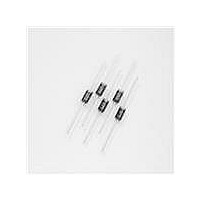
LCE24A Littelfuse Inc, LCE24A Datasheet - Page 2

LCE24A
Manufacturer Part Number
LCE24A
Description
DIODE TVS 24VR 1500W DO-201 5%
Manufacturer
Littelfuse Inc
Series
LCEr
Datasheet
1.LCE10.pdf
(5 pages)
Specifications of LCE24A
Package / Case
DO-201AA, DO-27, Axial
Voltage - Reverse Standoff (typ)
24V
Voltage - Breakdown
26.7V
Power (watts)
1500W
Polarization
Unidirectional
Mounting Type
Through Hole
Polarity
Unidirectional
Channels
1 Channel
Clamping Voltage
38.9 V
Operating Voltage
24 V
Breakdown Voltage
26.7 V
Termination Style
Through Hole
Peak Surge Current
39 A
Peak Pulse Power Dissipation
1500 W
Capacitance
100 pF
Maximum Operating Temperature
+ 175 C
Minimum Operating Temperature
- 55 C
Dimensions
5.3 mm Dia. x 5.2 (Max) mm W x 9.5 mm L
Lead Free Status / RoHS Status
Lead free by exemption / RoHS Compliant
Lead Free Status / RoHS Status
Lead free / RoHS Compliant, Lead free by exemption / RoHS Compliant
Other names
LCE24AT
Available stocks
Company
Part Number
Manufacturer
Quantity
Price
Company:
Part Number:
LCE24A
Manufacturer:
VISHAY
Quantity:
30 000
Note: For parts without A, the V
LCE Series
Number
LCE6.5A
LCE8.0A
LCE8.5A
LCE9.0A
Electrical Characteristics
LCE7 .0A
LCE7 .5A
LCE20A
LCE22A
LCE24A
LCE26A
LCE28A
LCE30A
LCE33A
LCE36A
LCE40A
LCE43A
LCE45A
LCE48A
LCE51A
LCE54A
LCE58A
LCE60A
LCE64A
LCE70A
LCE75A
LCE85A
LCE90A
LCE10A
LCE11A
LCE12A
LCE13A
LCE14A
LCE15A
LCE16A
LCE17A
LCE18A
Part
Stand off
Reverse
Voltage
V
10.0
12.0
13.0
14.0
15.0
16.0
18.0
20.0
22.0
24.0
26.0
28.0
30.0
33.0
36.0
40.0
43.0
45.0
48.0
54.0
58.0
60.0
64.0
70.0
75.0
85.0
90.0
51.0
11.0
17 .0
R
6.5
8.0
8.5
9.0
7 .0
7 .5
(V)
100.00 111.00
40.00
50.00
60.00
66.70
10.00
12.20
13.30
14.40
15.60
16.70
18.90
20.00
22.20
24.40
26.70
28.90
33.30
36.70
44.40
53.30
56.70
64.40
83.30
94.40 104.00
17 .80
31.10
47 .80
71.10
77 .80
Breakdown
MIN
11.10
Voltage V
8.33
8.89
9.44
BR
7 .22
7 .78
Transient Voltage Suppression Diodes
Axial Leaded – 1500W > LCE series
is ± 10%.
(V)
MAX
10.40
12.30
13.50
14.70
15.90
18.50
19.70
20.90
22.10
24.50
26.90
29.50
34.40
36.80
40.60
44.20
49.10
52.80
55.30
58.90
62.70
66.30
73.70
78.60
86.00
92.10
31.90
71.20
11.10
17 .20
8.60
9.21
9.83
7 .98
BR
Current
(mA)
Test
10
10
10
I
1
1
1
1
1
1
1
1
1
1
1
1
1
1
1
1
1
1
1
1
1
1
1
1
1
1
1
1
1
1
1
1
1
T
Maximum
Leakage
Reverse
I
R
1000
(μA)
500
250
100
@ V
50
10
5
1
1
1
1
1
1
1
1
1
1
1
1
1
1
1
1
1
1
1
1
1
1
1
1
1
1
1
1
1
R
Maximum
Clamping
Voltage
V
103.0
129.0
146.0
113.0
121.0
at I
12.0
12.9
13.6
14.4
15.4
18.2
19.9
23.2
24.4
26.0
29.2
32.4
35.5
38.9
42.1
45.5
48.4
53.3
58.1
64.5
69.4
72.7
82.4
93.6
96.8
11.2
21.5
27 .6
77 .4
87 .1
17 .0
Revision: January 09, 2009
C
(V)
pp
94
Maximum
Current
I
(Fig.3)
PPM
Pulse
100.0
100.0
100.0
100.0
100.0
Peak
88.0
82.0
75.0
70.0
65.0
54.0
46.0
42.0
39.0
36.0
33.0
28.1
25.8
23.3
20.6
19.4
18.2
16.0
15.5
61.0
51.0
31.0
21.6
14.6
13.3
12.4
10.3
97 .0
57 .0
17 .2
11.6
(A)
Capacitance
Maximum
@ 0 Volts
Junction
(pF)
100
100
100
100
100
100
100
100
100
100
100
100
100
100
100
100
100
100
100
100
100
100
100
100
100
100
100
100
100
100
100
100
100
100
100
100
Please refer to http://www.Littelfuse.com/series/LCE.html for current information.
Working
Blocking
Voltage
Inverse
V
WIB
100
100
100
100
125
125
125
125
75
75
75
75
75
75
75
75
75
75
75
75
75
75
75
75
75
75
75
75
75
75
75
75
75
75
75
75
(V)
Specifications are subject to change without notice.
Current at
Blocking
I
Leakage
Inverse
IB
(mA)
@ V
1.0
1.0
1.0
1.0
1.0
1.0
1.0
1.0
1.0
1.0
1.0
1.0
1.0
1.0
1.0
1.0
1.0
1.0
1.0
1.0
1.0
1.0
1.0
1.0
1.0
1.0
1.0
1.0
1.0
1.0
1.0
1.0
1.0
1.0
1.0
1.0
WIB
Blocking
Voltage
Inverse
V
Peak
PIB
100
100
100
100
100
100
100
100
100
100
100
100
100
100
100
100
100
100
100
100
100
100
100
100
100
100
100
100
125
125
125
125
150
150
150
150
(V)
©2009 Littelfuse, Inc.
Approval
Agency
X
X
X
X
X
X
X
X
X
X
X
X
X
X
X
X
X
X
X
X


