3130F120P7T1W02Q0.2A E-T-A, 3130F120P7T1W02Q0.2A Datasheet - Page 2
3130F120P7T1W02Q0.2A
Manufacturer Part Number
3130F120P7T1W02Q0.2A
Description
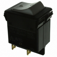
CIRCUIT BREAKER/SWITCH DP .2A
Manufacturer
E-T-A
Series
3130r
Datasheet
1.3130F120P7T1W02Q0.2A.pdf
(4 pages)
Specifications of 3130F120P7T1W02Q0.2A
Breaker Type
Thermal
Voltage
50VDC, 250VAC
Current - Trip (it)
200mA
Number Of Poles
2
Actuator Type
Rocker
Mounting Type
Panel Mount
Lead Free Status / RoHS Status
Lead free by exemption / RoHS compliant by exemption
Other names
302-1064
3130-F120-P7T1-W02Q-0.2AMP
3130F120P7T1W02Q0.2A
3130F120P7T1W02Q0.2AMP
3130-F120-P7T1-W02Q-0.2AMP
3130F120P7T1W02Q0.2A
3130F120P7T1W02Q0.2AMP


1
Type No.
3130
3130 - F 1 1 0 - P7 T1 - W 12 Q Y 7 - 5 A
*
**
*** without series resistor and diode, to be selected by customer.
1 - 76
Ordering information - 1-pole
N/A for non-illuminated version
unprotected poles have to ordered with terminal design N7
Recommendation:
4-7 V
10-14 V Rv 1.1 kΩ
20-28 V RV 2.7 kΩ
diode
rocker switch/circuit breaker
Mounting
F
snap in frame
Frame
1
3
standard
special single pole version
Number of poles
1
A
1N4007
Rv 0.43 kΩ
single pole, thermally protected
1-pole, unprotected**
Frame mounting
0
1
panel thickness 1-2.5 mm (.039-.099 in) (only 3130-F1..-...)
panel thickness 1.5-3.2 mm (.059-.126 in)(only 3130-F3.1-...)
Terminal design
P7
H7
N7
Thermal Overcurrent Circuit Breaker 3130
blade terminals DIN 46244-C-Ms-S (QC 2x.110)
for terminals 1.1, 2.1 3.1 terminal screws M 3.5
for terminals 1.2, 2.2, 3.1 blade terminals (QC 2x.110)
blade terminals (QC 2x.110), with shunt terminal
Characteristic curve
T1
Q1
thermal, 1.05-1.4 I
switch, only with terminal design -N7
Switch style
W
U
. 12 Q Y
. 14 Q R
. 19 Q Y
. 29 A G
rocker
momentary switch function
Switch colour designation
opaque
01
02
04
09
black
Rocker markings
A
Q
green
white
red
dot (ON position, only with switch
colour designation 29)
"I" and "O" moulded in
Rocker illumination (optional)
white rocker, yellow LED, AC/DC
red rocker, red LED, AC/DC
green rocker, yellow LED, AC/DC
black rocker with dot, green LED
Illumination voltage range*
(optional)
1
2
3
4
6
7
X
translucent
12
14
19
29
4 - 7 V
10 - 14 V
20 - 28 V
42 - 54 V
90 - 140 V
185 - 275 V (R,Y)
LED, DC 8 - 10 mA ***
Current ratings
0.1...20 A
N
white
red
green
black,
ordering example
rocker with green dot
(G,R,Y)
(G,R,Y)
(G,R,Y)
(R,Y)
(R,Y)
www.e-t-a.com
Type No.
3130
3130 - F 1 3 0 - P7 T1 - W 12 Q B 7 - 5 A
* N/A for non-illuminated version
**
Ordering information - multipole
unprotected poles have to ordered with terminal design N7
rocker switch/circuit breaker multipole
Mounting
F
snap in frame
Frame
1
standard
Number of poles
2
3
5
6
B
C
2-pole, thermally protected
3-pole, thermally protected
2-pole, thermally protected on one pole only
3-pole, thermally protected on two poles only
2-pole, unprotected**
3-pole, unprotected**
Frame mounting
0
panel thickness 1-2.5 mm (.039-.099 in) (only 3130-F1..-...)
Terminal design
P7
H7
N7
blade terminals DIN 46244-C-Ms-S (QC 2x.110)
for terminals 1.1, 2.1 3.1 terminal screws M 3.5;
for terminals 1.2, 2.2, 3.1 blade terminals
(QC 2x.110)
blade terminals DIN 46244-C-Ms-S (QC 2x.110),
with shunt terminal
Characteristic curve
T1
Q1
thermal, 1.05-1.4 I
switch, only with terminal design -N7
Switch style
W
U
rocker
momentary switch function
Switch colour designation
opaque
01
02
04
09
black
Rocker markings
Q
green
white
red
"I" and "O" moulded in
Rocker illumination (optional)
B
G
R
Y
filament (≤ AC/DC 48 V),
neon (≥ AC 115 V)
green LED, DC
red LED, DC
yellow LED, DC
Illumination voltage range*
(optional)
1
2
3
4
6
7
8
4 - 7 V
10 - 14 V (B,G,R,Y)
20 - 28 V (B,G,R,Y
42 - 54 V (B,R,Y
90 - 140 V
185 - 275 V (B)
320 - 450 V (B)
Current ratings
0.1...16 A
N
translucent
12
14
19
ordering example
white
red
green
(B,G,R,Y)
(B)
Issue B
Related parts for 3130F120P7T1W02Q0.2A
Image
Part Number
Description
Manufacturer
Datasheet
Request
R

Part Number:
Description:
CIRCUIT PROTECTOR; 10 A CLASS I, DIVISION 2 ; RESET INPUT AND STATUS OUTPUT ; 24
Manufacturer:
E-T-A Circuit Protection and Control
Datasheet:
Part Number:
Description:
Circuit Breaker; Therm; Push; Cur-Rtg 2A; PCB; 1 Pole; Vol-Rtg 240/28VAC/VDC
Manufacturer:
E-T-A Circuit Protection and Control
Datasheet:
Part Number:
Description:
Circuit Breaker; Therm; Push; Cur-Rtg 8A; Panel/PCB; 1 Pole; Vol-Rtg 240/28VAC/VDC
Manufacturer:
E-T-A Circuit Protection and Control
Datasheet:
Part Number:
Description:
Circuit Breaker; Therm; Push; Cur-Rtg 1A; Panel/PCB; 1 Pole; Vol-Rtg 240/28VAC/VDC
Manufacturer:
E-T-A Circuit Protection and Control
Datasheet:
Part Number:
Description:
Circuit Breaker; Therm; Push; Cur-Rtg 1.5A; Panel/PCB; 1 Pole; Vol-Rtg 240/28VAC/VDC
Manufacturer:
E-T-A Circuit Protection and Control
Datasheet:
Part Number:
Description:
Circuit Breaker; Therm; Push; Cur-Rtg 2A; Panel/PCB; 1 Pole; Vol-Rtg 240/28VAC/VDC
Manufacturer:
E-T-A Circuit Protection and Control
Datasheet:
Part Number:
Description:
Circuit Breaker; Therm; Push; Cur-Rtg 3.15A; Panel/PCB; 1 Pole; Vol-Rtg 240/28VAC/VDC
Manufacturer:
E-T-A Circuit Protection and Control
Datasheet:
Part Number:
Description:
Circuit Breaker; Therm; Push; Cur-Rtg 6.3A; Panel/PCB; 1 Pole; Vol-Rtg 240/28VAC/VDC
Manufacturer:
E-T-A Circuit Protection and Control
Datasheet:
Part Number:
Description:
Circuit Breaker; Therm; Push; Cur-Rtg 2.5A; Panel/PCB; 1 Pole; Vol-Rtg 240/28VAC/VDC
Manufacturer:
E-T-A Circuit Protection and Control
Datasheet:
Part Number:
Description:
Circuit Breaker; Therm; Push; Cur-Rtg 3.15A; PCB; 1 Pole; Vol-Rtg 240/28VAC/VDC
Manufacturer:
E-T-A Circuit Protection and Control
Datasheet:
Part Number:
Description:
Circuit Breaker; Therm; Push; Cur-Rtg 5A; PCB; 1 Pole; Vol-Rtg 240/28VAC/VDC
Manufacturer:
E-T-A Circuit Protection and Control
Datasheet:
Part Number:
Description:
Circuit Breaker; Therm; Push; Cur-Rtg 1A; PCB; 1 Pole; Vol-Rtg 240/28VAC/VDC
Manufacturer:
E-T-A Circuit Protection and Control
Datasheet:

Part Number:
Description:
CIRCUIT BREAKER VERT PCB 8A
Manufacturer:
E-T-A
Datasheet:
Part Number:
Description:
CIRCUIT BREAKER VERT PCB 5A
Manufacturer:
E-T-A
Datasheet:
Part Number:
Description:
Circuit Breaker, Single Pole, 250VAC 48 VDC, 0.05A
Manufacturer:
E-T-A Circuit Protection & Control