3120-F321-P7T1-W02D-16A E-T-A, 3120-F321-P7T1-W02D-16A Datasheet - Page 14
3120-F321-P7T1-W02D-16A
Manufacturer Part Number
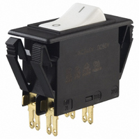
3120-F321-P7T1-W02D-16A
Description
CIRCUIT BREAKER ROCKR DP 16A WHT
Manufacturer
E-T-A
Series
3120-Fr
Datasheet
1.3120-F311-P7T1-W01D-20A.pdf
(16 pages)
Specifications of 3120-F321-P7T1-W02D-16A
Breaker Type
Thermal
Voltage
50VDC, 250VAC
Current - Trip (it)
16A
Number Of Poles
2
Actuator Type
Rocker
Mounting Type
Panel Mount
Lead Free Status / RoHS Status
Lead free / RoHS compliant by exemption
Other names
302-1223
3120-F321-P7T1-W02D-16AMP
3120-F321-P7T1-W02D-16AMP


1
A module suitable for all double pole versions of type 3120-F to trip
the main switch/circuit breaker mechanism in the event of loss of
voltage. When the voltage is restored the rocker switch must be reset
to reconnect the load, thereby avoiding the safety hazards associated
with automatic re-starting of machinery.
Note: Basic unit 3120-...-H7 or -G7: screw terminals necessary.
Machines such as power tools, industrial equipment and domestic
appliances where automatic restart after restoration of power could be
dangerous (EC Machinery Directive).
Type No.
X3120
X3120 - U 00 00
Authority
VDE (EN 60934)
UL, CSA
1 - 72
Description
Typical applications
Ordering information
Approvals (complete circuit breaker/module assembly)
Module for type 3120
Function
U
undervoltage release module
Terminal design
00
01
02
standard (without separate connections)
1 blade terminal 2.8x0.8 (QC .110)
2 blade terminals 2.8x0.8 (QC .110)
Voltage ratings
00
01
02
03
AC 230/240 V 50/60 Hz
AC 120 V 50/60 Hz
AC 100 V 50/60 Hz
DC 24 V
Assembly status
M
M
module mounted to the circuit breaker 3120
Undervoltage Release Module X3120-U...for circuit breaker 3120-F...
Voltage ratings
AC 100...240 V; DC 24 V
AC 100...240 V; DC 24 V
ordering example
www.e-t-a.com
Voltage ratings
Voltage tolerance
Current consumption
Typical life
Release values
Release delay
Latch-in values
Ambient temperature
Vibration
Shock
Corrosion
Humidity
Mass
This is a metric design and millimeter dimensions take precedence ( mm )
All dimensions without tolerances are for reference only. In the interest of improved design,
performance and cost effectiveness the right to make changes in these specifications
without notice is reserved.Product markings may not be exactly as the ordering codes.
Errors and omissions excepted.
Dimensions
Internal connection diagrams
Technical data
.260
6.6
X3120-U00…
12(k)
12(i)
11
23.5
.925
.866
.827
22
load
line
21
flat head screw M3.5x5-MS ISO1580
for mains connection
tightening torque max. 0.8 Nm
22(k)
21
22(i)
2 terminals
X3120-U02…
.421
Without terminal(s): X3120-U00…
10.7
X3120-U01…
AC 100; 120 V; 230/240 V 50/60 Hz
DC 24 V
+10%/-15%
approx. 2.5 mA
20,000 operations
0.2 x U
(at a rated voltage of AC 100 V the
device may release at 70 V and
must release at 20 V)
t < 20 ms
≥ 85 % U
-30...+60 °C (-22...+140 °F)
8 g (57-500 Hz) ± 0.61 mm (10-57 Hz)
to IEC 60068-2-6, test Fc
10 frequency cycles/axis
30 g (11 ms)
to IEC 60068-2-27, test Ea
48 hours at 5 % salt mist,
to IEC 60068-2-11, test Ka
240 hours at 95% RH
to IEC 60068-2-78, test Cab
approx. 53 g (complete assembly)
12(k)
12(i)
line
11
load
.827
A2s
N
21
line
< U < 0.7 x U
N
1 terminal
X3120-U01…
22(k)
21
22(i)
blade terminal
DIN 46244-A2.8-0.8
(QC .110)
X3120-U02…
12(k)
12(i)
N
11
inch
1.61
line
41
Issue B
+0.1
- 0.2
+.004
- .008
A1 A2
load
line
(230209)
22(k)
21
22(i)
Related parts for 3120-F321-P7T1-W02D-16A
Image
Part Number
Description
Manufacturer
Datasheet
Request
R

Part Number:
Description:
CIRCUIT BREAKER ROCKER DP12A
Manufacturer:
E-T-A
Datasheet:
Part Number:
Description:
CIRCUIT BREAKER DP 10A WHT ILL
Manufacturer:
E-T-A
Datasheet:
Part Number:
Description:
CIRCUIT BRKR ROCKER 2P 2.5A RED
Manufacturer:
E-T-A
Datasheet:
Part Number:
Description:
CIRCUIT BREAKER ROCKER DP 5A BK
Manufacturer:
E-T-A
Datasheet:
Part Number:
Description:
CIRCUIT BRKER RCKR DP 15A GRN
Manufacturer:
E-T-A
Datasheet:
Part Number:
Description:
CIRCUIT BREAKER DP 10A GRN LED
Manufacturer:
E-T-A
Datasheet:
Part Number:
Description:
CIRCUIT BREAKER DP 10A GREEN ILL
Manufacturer:
E-T-A
Datasheet:

Part Number:
Description:
CIRCUIT BREAKER ROCKER DP 10A BK
Manufacturer:
E-T-A
Datasheet:
Part Number:
Description:
CIRCUIT BREAKER ROCKER 15 AMP
Manufacturer:
E-T-A
Datasheet:

Part Number:
Description:
CIRCUIT BREAKER ROCKR DP 15A WHT
Manufacturer:
E-T-A
Datasheet:
Part Number:
Description:
CIRCUIT BREAKER ROCKR DP 20A WHT
Manufacturer:
E-T-A
Datasheet:
Part Number:
Description:
CIRCUIT BREAKER ROCKER DP 20A BK
Manufacturer:
E-T-A
Datasheet:

Part Number:
Description:
CIRCUIT BREAKER VERT PCB 8A
Manufacturer:
E-T-A
Datasheet:
Part Number:
Description:
CIRCUIT BREAKER VERT PCB 5A
Manufacturer:
E-T-A
Datasheet:
Part Number:
Description:
Circuit Breaker, Single Pole, 250VAC 48 VDC, 0.05A
Manufacturer:
E-T-A Circuit Protection & Control