3120-F321-P7T1-W02D-16A E-T-A, 3120-F321-P7T1-W02D-16A Datasheet - Page 9
3120-F321-P7T1-W02D-16A
Manufacturer Part Number
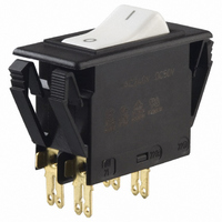
3120-F321-P7T1-W02D-16A
Description
CIRCUIT BREAKER ROCKR DP 16A WHT
Manufacturer
E-T-A
Series
3120-Fr
Datasheet
1.3120-F311-P7T1-W01D-20A.pdf
(16 pages)
Specifications of 3120-F321-P7T1-W02D-16A
Breaker Type
Thermal
Voltage
50VDC, 250VAC
Current - Trip (it)
16A
Number Of Poles
2
Actuator Type
Rocker
Mounting Type
Panel Mount
Lead Free Status / RoHS Status
Lead free / RoHS compliant by exemption
Other names
302-1223
3120-F321-P7T1-W02D-16AMP
3120-F321-P7T1-W02D-16AMP


Switch/thermal trip free circuit breaker (S-type TO CBE to EN 60934) with
standard isolator style two button operation. Single button press-to-reset
version also available. Both types can be supplied in single pole configuration
only, in double pole with single pole protection, and in double pole with
protection on both poles. Designed for snap-in panel mounting. There is a
choice of push button colour combinations and illumination is optional.
Any one of the following additional function modules can be supplied factory
fitted to the rear of the switch/circuit breaker:
●
●
●
●
●
Approved to CBE standard EN 60934 (IEC 60934).
Meets the requirements regarding fire resistance of EN 60335-1 : 2007-02
Safety of household and similar electrical appliances.
Motors, transformers, solenoids, extra low voltage wiring systems, office
machines, electro-medical equipment, power supplies, communications
systems, industrial controls.
Current
rating (A) per pole (Ω)
0.1
0.2
0.3
0.4
0.5
0.6
0.8
1
1.2
1.5
2
2.5
3
3.5
operating voltage
6 V
12 V
24 V
48 V
115 V
230 V
* single pole version only
Authority
VDE (EN 60934)
UL, CSA
CCC
Issue B
Description
Typical applications
Standard current ratings and typical internal resistance values
Illumination voltage/power consumption
Approvals
Under voltage release coil (for double pole versions only).
Magnetic trip coil for short circuit protection.
Magnetic trip coil for remote relay trip.
Auxiliary contacts for status signalling.
Mechanical slide interlock.
(230209)
Internal resistance
94
24
12
5.30
4.20
2.90
1.50
0.9
0.80
0.45
0.27
0.0785
0.0595
0.0565
Thermal Overcurrent Circuit Breaker 3120-F...
Voltage ratings
AC 240 V; DC 28 V
DC 50 V
DC 50 V
AC 250 V; DC 50 V
AC 250 V; DC 50 V
filament/neon
60 mA
20 mA
20 mA
20 mA
< 1.5 mA
< 1.5 mA
power consumption
Current
rating (A) per pole (Ω)
4
4.5
5
6
7
8
10
12
14
15
16
18
20
Internal resistance
0.0435
0.0435
0.0325
0.0215
0.0165
0.0165
< 0.02
< 0.02
< 0.02
< 0.02
< 0.02
< 0.02
< 0.02
Current ratings
0.1...20 A
0.1...20 A 2-pole
0.1...10 A 1-pole
0.1...20 A
0.1...20 A
LED
9 mA
9 mA
9 mA
1.5 mA
< 1 mA*
< 1 mA*
www.e-t-a.com
Current ratings
Dielectric strength
(IEC 60664 and 60664A)
Interrupting capacity
Degree of protection
Shock
Corrosion
Humidity
Mass
For further details please see chapter: Technical Information
Voltage rating
Typical life
Ambient temperature
Insulation co-ordination
(IEC 60664 and 60664 A
Insulation resistance
Interrupting capacity I
(UL 1077)
(IEC 60529/DIN 40050)
Vibration
Technical data
AC 240 V:
DC 50 V:
DC 28 V:
AC 415 V:
AC 240 V:
DC 50 V:
operating area
between poles (2-pole)
0.1...20 A 30,000 operations at 1 x I
0.1...4 A
4.5...16 A 30,000 operations at 1 x I
4.5...20 A 30,000 operations at 1 x I
0.1...16 A 10,000 operations at 1 x I
0.1...16 A 50,000 operations at 1 x I
17...20 A
0.1...16 A 50,000 operations at 1 x I
17...20 A
cn
AC 240 V; DC 50 V
(AC 415 V to special order)
(UL: AC 250 V; DC 50 V)
0.1...20 A
(up to 30 A to special order, single pole only)
1-pole
30,000 operations at 1 x I
2-pole
30,000 operations at 1 x I
10,000 operations at 1 x I
-30...+60 °C (-22...+140 °F)
rated impulse
withstand voltage
2.5 kV
reinforced insulation in operating area
test voltage
AC 3,000 V
AC 1,500 V
> 100 MΩ (DC 500 V)
0.1...2 A 10 x I
2.5...20 A 250 A 2-pole, or 150 A 1-pole
I
0.1...2 A
2.5...3 A
3.5...8 A
9...16 A
18...20 A
0.1...20 A
operating area IP40
terminal area IP00
8 g (57-500 Hz), ± 0.61 mm (10-57 Hz)
to IEC 60068-2-6, test Fc
10 frequency cycles/axis
30 g (11 ms)
to IEC 60068-2-27, test Ea
96 hours at 5 % salt mist,
to IEC 60068-2-11, test Ka
240 hours at 95 % RH,
to IEC 60068-2-78, test Cab
approx. 33 g (double pole)
approx. 27 g (single pole)
N
3120-F...
U
AC 250 V
AC 250 V
AC 250 V
AC 250 V
AC 250 V
DC 50 V
N
N
pollution
degree
2
N
N
N
N
N
N
N
N
N
, inductive
, inductive
, resistive
, inductive
, inductive
, inductive
, inductive
, inductive
, inductive
2-pole
200 A
1,000 A
2,000 A
3,500 A
5,000 A
1,000 A
1 - 67
67
1
Related parts for 3120-F321-P7T1-W02D-16A
Image
Part Number
Description
Manufacturer
Datasheet
Request
R

Part Number:
Description:
CIRCUIT BREAKER ROCKER DP12A
Manufacturer:
E-T-A
Datasheet:
Part Number:
Description:
CIRCUIT BREAKER DP 10A WHT ILL
Manufacturer:
E-T-A
Datasheet:
Part Number:
Description:
CIRCUIT BRKR ROCKER 2P 2.5A RED
Manufacturer:
E-T-A
Datasheet:
Part Number:
Description:
CIRCUIT BREAKER ROCKER DP 5A BK
Manufacturer:
E-T-A
Datasheet:
Part Number:
Description:
CIRCUIT BRKER RCKR DP 15A GRN
Manufacturer:
E-T-A
Datasheet:
Part Number:
Description:
CIRCUIT BREAKER DP 10A GRN LED
Manufacturer:
E-T-A
Datasheet:
Part Number:
Description:
CIRCUIT BREAKER DP 10A GREEN ILL
Manufacturer:
E-T-A
Datasheet:

Part Number:
Description:
CIRCUIT BREAKER ROCKER DP 10A BK
Manufacturer:
E-T-A
Datasheet:
Part Number:
Description:
CIRCUIT BREAKER ROCKER 15 AMP
Manufacturer:
E-T-A
Datasheet:

Part Number:
Description:
CIRCUIT BREAKER ROCKR DP 15A WHT
Manufacturer:
E-T-A
Datasheet:
Part Number:
Description:
CIRCUIT BREAKER ROCKR DP 20A WHT
Manufacturer:
E-T-A
Datasheet:
Part Number:
Description:
CIRCUIT BREAKER ROCKER DP 20A BK
Manufacturer:
E-T-A
Datasheet:

Part Number:
Description:
CIRCUIT BREAKER VERT PCB 8A
Manufacturer:
E-T-A
Datasheet:
Part Number:
Description:
CIRCUIT BREAKER VERT PCB 5A
Manufacturer:
E-T-A
Datasheet:
Part Number:
Description:
Circuit Breaker, Single Pole, 250VAC 48 VDC, 0.05A
Manufacturer:
E-T-A Circuit Protection & Control