PT06E-12-8P(SR) Amphenol Industrial Operations, PT06E-12-8P(SR) Datasheet - Page 79
PT06E-12-8P(SR)
Manufacturer Part Number
PT06E-12-8P(SR)
Description
CONN PLUG 8POS W/PINS SOLDER
Manufacturer
Amphenol Industrial Operations
Series
MIL-DTL-26482 Series I, PTr
Type
Cable Plugr
Specifications of PT06E-12-8P(SR)
Connector Type
Plug, Male Pins
Number Of Positions
8
Shell Size - Insert
12-8
Mounting Type
Free Hanging (In-Line)
Termination
Solder Cup
Fastening Type
Bayonet Lock
Orientation
N (Normal)
Ingress Protection
Environment Resistant
Shell Material, Finish
Aluminum, Olive Drab Cadmium Plated
Features
Strain Relief
Agency Approvals
UL Recognized
Angle
Straight
Application
Commercial
Brand/series
PT Series
Class
E
Contact Configuration
8#20
Contact Plating
Gold
Contact Type
Pin
Current, Rating
7.5 A
Finish, Housing
Olive Drab Cadmium
Housing Type
Metal
Insert Arrangement
12-8
Material, Dielectric
Neoprene
Material, Housing
Aluminum
Mating Type
Bayonet
Number Of Contacts
8
Primary Type
26482 Commercial
Shell Size
12
Special Features
5 Key/Keyway Polarization
Strain Relief
External
Voltage, Rating
600 VAC
Wire, Awg
20
Lead Free Status / RoHS Status
Contains lead / RoHS non-compliant
Shell Size, Military
-
Other names
PT06E12-8P(SR)


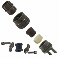
Mounting Recommendations
for miniature cylindrical connectors
FLANGE MOUNTED CONNECTORS
All flange mounting PC and PT connectors use standard MS
mounting dimensions. They cannot be back panel mounted
due to coupling clearance. The PTB (thru-bulkhead) type con-
nector must also be back panel mounted on one side. Flange
gaskets are available for both series, see page 64.
JAM NUT MOUNTINGS
The jam nut design has become very popular because it allows
bench wiring of harness assemblies. The labor saving often off-
sets the added cost of the jam nut receptacle which is due to
the self contained “O” ring and the extra nut. The PC series
mounts in a round hole and can be pinned to prevent rotation.
The PT series mounts in a “D” mounting hole and does not
require pinning.
HERMETIC RECEPTACLE MOUNTINGS
This series must be mounted in such a way as to preserve the
hermetic seal provided by the glass insert. Mounting data for
box and jam nut receptacles is given above. Cut-out required
for solder mounting receptacles (N) is given below.
Shell
Shell
Shell
Size
Size
Size
10
12
14
16
18
20
22
24
10
12
14
16
18
20
22
24
10
12
14
16
18
20
22
6
8
6
8
6
8
PC & PT
1.062
1.156
1.250
1.375
1.007
1.134
1.259
1.384
1.507
1.634
1.051
1.176
1.395
1.375
+.010
–.000
Max.
.469
.594
.719
.812
.906
.969
.447
.572
.697
.884
.458
.582
.692
.801
.926
R
N
(TP)
R
1.031
1.125
1.203
1.297
1.375
1.084
1.208
1.333
1.459
+.000
1.575
–.010
.641
.734
.812
.938
.420
.542
.669
.830
.955
SP
B
–
The finish of each of these hermetic
receptacles is fused electro-deposited
tin for easy solderability, and protected
by a special lacquer for optimum shelf
life. The lacquer will not interfere with
any soldering operation.
Low temperature solder should be used
and the addition of a solder fillet at
arrow points on drawing at right is rec-
ommended. Care must be taken that
the operating temperature of the final
assembly does not rise above the melt-
PC & PT
1.073
1.199
1.323
1.449
±.010
.323
.449
.573
.699
.823
.949
.286
.331
.375
.442
.486
.530
.573
.641
.685
F
–
Dia.
D
Panel Thickness
1.108
1.233
1.358
1.483
.062
Min.
.439
.563
.680
.859
.984
.062
.062
.062
.062
.062
.062
.062
.062
.062
SP
–
P
Max.
.250
.125
.125
.125
.125
.125
.125
.125
.250
.250
R
2
CUT-OUT FOR
CUT-OUT
R
PT ONLY
77
N
B
R
2
(TP)
R
D Dia.
F
FLANGE MOUNTED CONNECTORS
RECEPTACLE
PIN LOCATION FOR PC ONLY
CUT-OUT
SOLDER
JAM NUT MOUNTINGS
HERMETIC RECEPTACLES
F
4 HOLES
.120 Dia. for Shell Sizes 6-22
.147 Dia. for
.150 Dia. for
PC & PT
Size 24 PT
SP only
(See dimensions
RECEPTACLE
JAM NUT
above)
(See dimensions
SECTION
RECEPTACLE
above)
SECTION
BOX
No. 4 Screw
for PC & PT
No. 6 Screw
for SP and for
Size 24 PT
Related parts for PT06E-12-8P(SR)
Image
Part Number
Description
Manufacturer
Datasheet
Request
R

Part Number:
Description:
connector, straight plug, class e, size 12, 4 #16 solder pin contact
Manufacturer:
Amphenol Industrial Operations
Datasheet:

Part Number:
Description:
CONN PLUG 8POS W/SOCKET SOLDER
Manufacturer:
Amphenol Industrial Operations
Datasheet:

Part Number:
Description:
CONN PLUG 8POS W/PINS SOLDER
Manufacturer:
Amphenol Industrial Operations
Datasheet:
Part Number:
Description:
CONN PLUG 8POS W/SOCKET SOLDER
Manufacturer:
Amphenol Industrial Operations
Datasheet:
Part Number:
Description:
CONN PLUG 10 POS STRAIGHT W/SCKT
Manufacturer:
Amphenol Industrial Operations
Datasheet:

Part Number:
Description:
JAM NUT CONN, RCPT, SIZE 9, 6POS, PANEL
Manufacturer:
Amphenol Industrial Operations
Datasheet:
Part Number:
Description:
PT 41C 41#20 PIN RECP
Manufacturer:
Amphenol Industrial Operations
Part Number:
Description:
PT 41C 41#20 SKT RECP
Manufacturer:
Amphenol Industrial Operations