NRS5020T150MMGJ Taiyo Yuden, NRS5020T150MMGJ Datasheet - Page 13
NRS5020T150MMGJ
Manufacturer Part Number
NRS5020T150MMGJ
Description
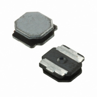
INDUCTOR 15UH 1.2A 20% SMD
Manufacturer
Taiyo Yuden
Series
NRSr
Type
Ferrite Corer
Datasheet
1.NRS5014T1R2NMGG.pdf
(16 pages)
Specifications of NRS5020T150MMGJ
Inductance
15µH
Current
1.2A
Current - Saturation
1.1A
Current - Temperature Rise
1.2A
Tolerance
±20%
Shielding
Shielded
Dc Resistance (dcr)
198 mOhm Max
Self Resonant Freq
20MHz
Package / Case
2008 (5020 Metric)
Mounting Type
Surface Mount
Operating Temperature
-25°C ~ 120°C
Frequency - Test
100kHz
Material - Core
Ferrite
Applications
Power Supplies
Lead Free Status / RoHS Status
Lead free / RoHS Compliant
Q @ Freq
-
Other names
587-2410-2
Available stocks
Company
Part Number
Manufacturer
Quantity
Price
Company:

Part Number:
NRS5020T150MMGJ
Manufacturer:
TAIYO
Quantity:
40 000
Company:
Part Number:
NRS5020T150MMGJ
Manufacturer:
TAIYO YUDEN
Quantity:
66 000


【Test Method and Remarks】
【Test Method and Remarks】
【Test Method and Remarks】
【Test Method and Remarks】
■
Wound Chip power inductor (NR, NS-series)
* This catalog contains the typical specification only due to the limitation of space. When you consider the purchase of our products, please check our specification.
wound0407_reli_e-01
NR30/40/50/60/80, NRV30, NRH24/30,
NRS40/50/60/80 Type
NR10050 Type
NS12555, NS12565, NS12575Type
NR30/40/50/60/80, NRV30, NRH24/30,
NRS40/50/60/80 Type
NR10050 Type
NS12555, NS12565, NS12575Type
NR30/40/50/60/80, NRV30, NRH24/30,
NRS40/50/60/80 Type
NR10050 Type
NS12555, NS12565, NS12575Type
NR30/40/50/60/80, NRV30, NRH24/30,
NRS40/50/60/80 Type
NR10050 Type
NS12555, NS12565, NS12575Type
NR30/40/50/60/80, NRV30, NRH24/30, NRS40/50/60/80 Type, NS12555, NS12565, NS12575 Type :
NR10050 Type :
NR30/40/50/60/80, NRV30, NRH24/30,
NRS40/50/60/80 Type
NR10050 Type
NS12555, NS12565, NS12575Type
NR30/40/50/60/80, NRV30, NRH24/30, NRS40/50/60/80 Type, NR10050 Type, NS12555, NS12565, NS12575Type :
NR30/40/50/60/80, NRV30, NRH24/30,
NRS40/50/60/80 Type
NR10050 Type
NS12555, NS12565, NS12575Type
NR30/40/50/60/80, NRV30, NRH24/30, NRS40/50/60/80 Type, NS12555, NS12565, NS12575 Type :
※Immersion depth : All sides of mounting terminal shall be immersed.
NR30/40/50/60/80, NRV30, NRH24/30,
NRS40/50/60/80 Type
NR10050 Type
NS12555, NS12565, NS12575Type
NR30/40/50/60/80, NRV30, NRH24/30, NRS40/50/60/80 Type, NR10050 Type, NS12555, NS12565, NS12575 Type :
NR6020 Type :
Test board thickness : 1.0mm (NR30/40/50/60/80, NRV30, NRH24/30, NRS40/50/60/80 Type, NS12555, NS12565, NS12575 Type)
Test board material
9. Insulation resistance : between wires
10. Insulation resistance : between wire and core
11. Withstanding voltage : between wire and core
12. Adhesion of terminal electrode
13. Resistance to vibration
14. Solderability
15. Resistance to soldering heat
For details of each product (characteristics graph, reliability information, precautions for use, and so on), see our Web site (http://www.ty-top.com/) or CD catalogs.
RELIABILITY DATA
・ Applied force
・ Duration
・ Solder cream thickness : 0.15mm.
・ Applied force : 5N to X and Y directions.
・ Duration
The test samples shall be soldered to the test board by the reflow.
The test samples shall be soldered to the test board by the reflow.
Then it shall be submitted to below test conditions.
Recovery : At least 2hrs of recovery under the standard condition after the test, followed by the measurement within 48hrs.
The test samples shall be dipped in flux, and then immersed in molten solder as shown in below table.
Flux : Methanol solution containing rosin 25%.
The test sample shall be exposed to reflow oven at 230±5℃ for 40 seconds, with peak temperature at 260±5℃ for 5 seconds, 2 times.
The test sample shall be exposed to reflow oven at 230±5℃ for 40 seconds, with peak temperature at 250
Solder Temperature
Sweeping Method
Frequency Range
Total Amplitude
Time
Time
: 5s.
: glass epoxy-resin
1.6mm (NR10050 Type)
10~55Hz
1.5mm (May not exceed acceleration 196m/s
10Hz to 55Hz to 10Hz for 1min.
5±1.0 sec.
: 10N to X and Y directions.
: 5s.
245±5℃
X
Y
Z
For 2 hours on each X, Y, and Z axis.
Shall not come off PC board
Inductance change : Within ±10%
No significant abnormality in appearance.
At least 90% of surface of terminal electrode is covered by new solder.
Inductance change : Within ±10%
No significant abnormality in appearance.
2
)
10N, 5s
1
+5
ー0
℃ for 5 seconds, 2 times.
wound0407_reli-RP2
Related parts for NRS5020T150MMGJ
Image
Part Number
Description
Manufacturer
Datasheet
Request
R

Part Number:
Description:
Manufacturer:
Taiyo Yuden
Datasheet: