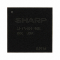
LH7A404N0E000B0A Sharp Microelectronics, LH7A404N0E000B0A Datasheet - Page 26

LH7A404N0E000B0A
Manufacturer Part Number
LH7A404N0E000B0A
Description
IC ARM922T MCU 200MHZ 324CABGA
Manufacturer
Sharp Microelectronics
Series
BlueStreak ; LH7Ar
Specifications of LH7A404N0E000B0A
Core Processor
ARM9
Core Size
32-Bit
Speed
200MHz
Connectivity
Audio CODEC, EBI/EMI, IrDA, MMC, SmartCard, SSP, UART/USART, USB
Peripherals
AC'97, DMA, LCD, POR, PWM, WDT
Number Of I /o
64
Program Memory Type
ROMless
Ram Size
80K x 8
Voltage - Supply (vcc/vdd)
1.71 V ~ 3.6 V
Data Converters
A/D 9x10b
Oscillator Type
Internal
Operating Temperature
-40°C ~ 85°C
Package / Case
324-CABGA
For Use With
568-4304 - BOARD EVAL FOR LH7A404
Lead Free Status / RoHS Status
Contains lead / RoHS non-compliant
Eeprom Size
-
Program Memory Size
-
Other names
425-1868
LH7A404N0E000
LH7A404N0E000
Available stocks
Company
Part Number
Manufacturer
Quantity
Price
Company:
Part Number:
LH7A404N0E000B0A
Manufacturer:
Sharp Microelectronics
Quantity:
10 000
LH7A404
Color LCD Controller
support up to 1,024 × 768, 16-bit color LCD panels. It
interfaces directly to STN, color STN, TFT, AD-TFT,
and HR-TFT panels. Unlike other LCD controllers, the
LH7A404’s LCD Controller saves an external timing
ASIC by incorporating the timing conversion logic for
thin LCD modules such as AD-TFT and HR-TFT.
• Up to 1,024 × 768 Resolution
• 16-bit Video Bus
• 16 bits-per-pixel (bpp) 5:5:5:1 or 5:6:5 direct color or
• STN, Color STN, AD-TFT, HR-TFT, TFT panels
AC97 Codec Controller
interface to an external audio codec. The AC97 link is a
bi-directional, fixed rate, serial Pulse Code Modulated
(PCM) digital stream, dividing each audio frame into 12
outgoing and 12 incoming data streams (slots), each
with 20-bit resolution per sample.
AC97 link to the audio codec and an interface to the
AMBA APB.
• Serial-to-parallel conversion for data received from
• Parallel-to-serial conversion for data transmitted to
• Reception/transmission of control and status infor-
• Support for up to 4 simultaneous codec sampling
Audio Codec Interface (ACI)
• A digital serial interface to an off-chip 8-bit codec
• All the necessary clocks and timing pulses to per-
26
on-chip color palette for 1, 2, 4, and 8 bpp resolution
the external codec
the external codec
mation via the AMBA APB interface
rates with its 4 transmit and 4 receive channels. The
transmit and receive paths are buffered with internal
FIFO memories, allowing data to be stored indepen-
dently in both transmit and receive modes. Three of
the outgoing FIFOs can be written via either the APB
interface or with DMA channels 1-3.
form serialization or de-serialization of the data
stream to, or from the codec device.
The LH7A404’s LCD Controller is programmable to
The Color LCD Controller features support for:
– Single and Dual Scan STN panels
– Up to 15 Gray Shades (mono STN)
– Up to 3375 colors (color STN)
– Up to 64 k-Colors
– An on-chip SRAM frame buffer conserves bus
The AC97 Codec controller includes a 5-pin serial
The AC97 controller contains logic that controls the
Its main features include:
The ACI provides:
bandwidth and saves active power.
Version 1.0
transmit and receive paths are buffered with internal
FIFO memories allowing up to 16 bytes to be stored
independently in both transmit and receive modes.
that generates a common transmit and receive bit clock
output from the on-chip ACI clock input (ACBITCLK).
Transmit data values are output synchronous with the
rising edge of the bit clock output. Receive data values
are sampled on the falling edge of the bit clock output.
The start of a data frame is indicated by a synchroniza-
tion output signal that is coincident with the bit clock.
Pulse Width Modulator (PWM)
• Configurable dual output
• Separate input clocks for each PWM output
• 16-bit resolution
• Programmable synchronous mode support allows
• Programmable pulse width (duty cycle), interval
input AMBA slave module, and connects to the APB.
Synchronous Serial Port (SSP)
nous serial communication with peripheral devices
that have either Motorola SPI, National Semicon-
d u c t o r M I C R O W I R E , o r T e x a s I n s t r u m e n t s
Synchronous Serial Interfaces.
data received from a peripheral. The transmit and
receive paths are buffered with internal FIFO memories
allowing up to eight 16-bit values to be stored indepen-
dently in both transmit and receive modes. Serial data
is transmitted on SSPTXD and received on SSPRXD.
clock divider and prescaler to generate the serial output
clock SCLK from the input clock SSPCLK. Bit rates are
supported to 2 MHz and beyond, subject to choice of
frequency for SSPCLK; the maximum bit rate will usu-
ally be determined by peripheral device’s capability.
external input to start PWM
(frequency), and polarity
The interface supports full duplex operation and the
The ACI includes a programmable frequency divider
The Pulse Width Modulator features:
– Static programming: when the PWM is stopped
– Dynamic programming: when the PWM is running
– Updates duty cycle, frequency, and polarity at
The PWM is a configurable dual-output, dual-clock-
The SSP is a master-only interface for synchro-
The SSP performs serial-to-parallel conversion on
The LH7A404 SSP includes a programmable bit rate
end of a PWM cycle
32-Bit System-on-Chip
Data Sheet


