R5F212G5SDFP#U0 Renesas Electronics America, R5F212G5SDFP#U0 Datasheet
R5F212G5SDFP#U0
Specifications of R5F212G5SDFP#U0
Available stocks


Related parts for R5F212G5SDFP#U0


R5F212G5SDFP#U0 Summary of contents
Page 1
To our customers, Old Company Name in Catalogs and Other Documents st On April 1 , 2010, NEC Electronics Corporation merged with Renesas Technology Corporation, and Renesas Electronics Corporation took over all the business of both companies. Therefore, although the ...
Page 2
All information included in this document is current as of the date this document is issued. Such information, however, is subject to change without any prior notice. Before purchasing or using any Renesas Electronics products listed herein, please confirm ...
Page 3
R8C/2G Group RENESAS MCU 1. Overview 1.1 Features The R8C/2G Group of single-chip MCUs incorporates the R8C/Tiny Series CPU core, employing sophisticated instructions for a high level of efficiency. With 1 Mbyte of address space, and it is capable of ...
Page 4
R8C/2G Group Table 1.1 Specifications for R8C/2G Group Item Function CPU Central processing unit Memory ROM, RAM Power Supply Voltage detection Voltage circuit Detection Comparator I/O Ports Clock Clock generation circuits Interrupts Watchdog Timer Timer Timer RA Timer RB Timer ...
Page 5
R8C/2G Group 1.2 Product List Table 1.2 lists Product List for R8C/2G Group, Figure 1.1 shows a Part Number, Memory Size, and Package of R8C/2G Group. Table 1.2 Product List for R8C/2G Group Part No. R5F212G4SNFP 16 Kbytes R5F212G5SNFP 24 ...
Page 6
R8C/2G Group 1.3 Block Diagram Figure 1.2 shows a Block Diagram. I/O ports Peripheral functions Timers Timer RA (8 bits) Timer RB (8 bits) Timer RE (8 bits) Timer RF (16 bits) Watchdog timer (15 bits) Figure 1.2 Block Diagram ...
Page 7
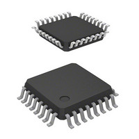
R8C/2G Group 1.4 Pin Assignment Figure 1.3 shows Pin Assignment (Top View). Table 1.3 outlines the Pin Name Information by Pin Number. P0_7/(Kl0) P0_6/INT4 P0_5 P0_4/(TREO) P6_3/TXD2 P6_0/TREO P6_6/(Kl1) P6_4/RXD2 NOTES: 1. Can be assigned to the pin in parentheses ...
Page 8
R8C/2G Group Table 1.3 Pin Name Information by Pin Number Pin Control Pin Port Number 1 P3_5 2 P3_7 3 RESET 4 XCOUT (P4_4) 5 VSS 6 XCIN (P4_3) 7 VCC 8 MODE 9 P4_5 10 P1_7 11 P3_6 12 ...
Page 9
R8C/2G Group 1.5 Pin Functions Table 1.4 lists Pin Functions. Table 1.4 Pin Functions Type Symbol Power supply input VCC, VSS Reset input RESET MODE MODE XCIN clock input XCIN XCIN clock output XCOUT INT interrupt input INT0 to INT2, ...
Page 10
R8C/2G Group 2. Central Processing Unit (CPU) Figure 2.1 shows the CPU Registers. The CPU contains 13 registers. R0, R1, R2, R3, A0, A1, and FB configure a register bank. There are two sets of register bank. b31 R2 R3 ...
Page 11
R8C/2G Group 2.1 Data Registers (R0, R1, R2, and R3 16-bit register for transfer, arithmetic, and logic operations. The same applies R3. R0 can be split into high-order bits (R0H) and low-order bits (R0L) ...
Page 12
R8C/2G Group 2.8.7 Interrupt Enable Flag (I) The I flag enables maskable interrupts. Interrupt are disabled when the I flag is set to 0, and are enabled when the I flag is set to 1. The I flag is set ...
Page 13
R8C/2G Group 3. Memory Figure 3 Memory Map of R8C/2G Group. The R8C/2G group has 1 Mbyte of address space from addresses 00000h to FFFFFh. The internal ROM is allocated lower addresses, beginning with address 0FFFFh. For example, ...
Page 14
R8C/2G Group 4. Special Function Registers (SFRs) An SFR (special function register control register for a peripheral function. Tables 4.1 to 4.12 list the special function registers. Table 4.1 SFR Information (1) Address 0000h 0001h 0002h 0003h 0004h ...
Page 15
R8C/2G Group Table 4.2 SFR Information (2) Address 0030h 0031h Voltage Detection Register 1 0032h Voltage Detection Register 2 0033h 0034h 0035h 0036h Voltage Monitor 1 Circuit Control Register 0037h Voltage Monitor 2 Circuit Control Register 0038h Voltage Monitor 0 ...
Page 16
R8C/2G Group Table 4.3 SFR Information (3) Address 0070h 0071h 0072h 0073h 0074h 0075h 0076h 0077h 0078h 0079h 007Ah 007Bh 007Ch 007Dh 007Eh 007Fh 0080h 0081h 0082h 0083h 0084h 0085h 0086h 0087h 0088h 0089h 008Ah 008Bh 008Ch 008Dh 008Eh 008Fh ...
Page 17
R8C/2G Group Table 4.4 SFR Information (4) Address 00B0h 00B1h 00B2h 00B3h 00B4h 00B5h 00B6h 00B7h 00B8h 00B9h 00BAh 00BBh 00BCh 00BDh 00BEh 00BFh 00C0h 00C1h 00C2h 00C3h 00C4h 00C5h 00C6h 00C7h 00C8h 00C9h 00CAh 00CBh 00CCh 00CDh 00CEh 00CFh ...
Page 18
R8C/2G Group Table 4.5 SFR Information (5) Address 00F0h 00F1h 00F2h 00F3h 00F4h 00F5h 00F6h Pin Select Register 2 00F7h Pin Select Register 3 00F8h Port Mode Register 00F9h External Input Enable Register 00FAh INT Input Filter Select Register 00FBh ...
Page 19
R8C/2G Group Table 4.6 SFR Information (6) Address 0130h 0131h 0132h 0133h 0134h 0135h 0136h 0137h 0138h 0139h 013Ah 013Bh 013Ch 013Dh 013Eh 013Fh 0140h 0141h 0142h 0143h 0144h 0145h 0146h 0147h 0148h 0149h 014Ah 014Bh 014Ch 014Dh 014Eh 014Fh ...
Page 20
R8C/2G Group Table 4.7 SFR Information (7) Address 0170h 0171h 0172h 0173h 0174h 0175h 0176h 0177h 0178h 0179h 017Ah 017Bh 017Ch 017Dh 017Eh 017Fh 0180h 0181h 0182h 0183h 0184h 0185h 0186h 0187h 0188h 0189h 018Ah 018Bh 018Ch 018Dh 018Eh 018Fh ...
Page 21
R8C/2G Group Table 4.8 SFR Information (8) Address 01B0h 01B1h 01B2h 01B3h Flash Memory Control Register 4 01B4h 01B5h Flash Memory Control Register 1 01B6h 01B7h Flash Memory Control Register 0 01B8h 01B9h 01BAh 01BBh 01BCh 01BDh 01BEh 01BFh 01C0h ...
Page 22
R8C/2G Group Table 4.9 SFR Information (9) Address 01F0h 01F1h 01F2h 01F3h 01F4h 01F5h 01F6h 01F7h 01F8h 01F9h 01FAh 01FBh 01FCh 01FDh 01FEh 01FFh 0200h 0201h 0202h 0203h 0204h 0205h 0206h 0207h 0208h 0209h 020Ah 020Bh 020Ch 020Dh 020Eh 020Fh ...
Page 23
R8C/2G Group Table 4.10 SFR Information (10) Address 0230h 0231h 0232h 0233h 0234h 0235h 0236h 0237h 0238h 0239h 023Ah 023Bh 023Ch 023Dh 023Eh 023Fh 0240h 0241h 0242h 0243h 0244h 0245h 0246h 0247h 0248h 0249h 024Ah 024Bh 024Ch 024Dh 024Eh 024Fh ...
Page 24
R8C/2G Group Table 4.11 SFR Information (11) Address 0270h 0271h 0272h 0273h 0274h 0275h 0276h 0277h 0278h 0279h 027Ah 027Bh 027Ch 027Dh 027Eh 027Fh 0280h 0281h 0282h 0283h 0284h 0285h 0286h 0287h 0288h 0289h 028Ah 028Bh 028Ch 028Dh 028Eh 028Fh ...
Page 25
R8C/2G Group Table 4.12 SFR Information (12) Address 02B0h 02B1h 02B2h 02B3h 02B4h 02B5h 02B6h 02B7h 02B8h 02B9h 02BAh 02BBh 02BCh 02BDh 02BEh 02BFh 02C0h 02C1h 02C2h 02C3h 02C4h 02C5h 02C6h 02C7h 02C8h 02C9h 02CAh 02CBh 02CCh 02CDh 02CEh 02CFh ...
Page 26
R8C/2G Group 5. Electrical Characteristics Table 5.1 Absolute Maximum Ratings Symbol Parameter V Supply voltage CC V Input voltage I V Output voltage O P Power dissipation d T Operating ambient temperature opr T Storage temperature stg Table 5.2 Recommended ...
Page 27
R8C/2G Group Table 5.3 Flash Memory (Program ROM) Electrical Characteristics Symbol Parameter − Program/erase endurance − Byte program time − Block erase time − Program, erase voltage − Read voltage − Program, erase temperature − (7) Data hold time NOTES: ...
Page 28
R8C/2G Group Table 5.4 Voltage Detection 0 Circuit Electrical Characteristics Symbol V Voltage detection level det0 − Voltage detection circuit self power consumption t Waiting time until voltage detection circuit operation d(E-A) (2) starts Vccmin MCU operating voltage minimum value ...
Page 29
R8C/2G Group Table 5.7 Power-on Reset Circuit, Voltage Monitor 0 Reset Electrical Characteristics Symbol Parameter V Power-on reset valid voltage por1 V Power-on reset or voltage monitor 0 reset valid por2 voltage t External power V rth CC NOTES: 1. ...
Page 30
R8C/2G Group Table 5.8 Comparator Electrical Characteristics Symbol Parameter Vref Internal reference voltage Vcref External input reference voltage Vcin External comparison voltage input range Vofs Input offset voltage Tcrsp Response time NOTE: 1. The measurement condition is T Table 5.9 ...
Page 31
R8C/2G Group Table 5.12 Electrical Characteristics (1) [V Symbol Parameter V Output “H” voltage OH V Output “L” voltage Hysteresis T+- T- INT0, INT1, INT2, INT4, KI0, KI1, KI2, KI3, RXD0, RXD2, CLK0, CLK2 RESET I Input ...
Page 32
R8C/2G Group Table 5.13 Electrical Characteristics (2) [Vcc = 5 V] − 85°C (N version) / opr Symbol Parameter I Power supply current High-speed 3.3 to 5.5 V) on-chip oscillator mode CC Single-chip ...
Page 33
R8C/2G Group Timing Requirements (Unless Otherwise Specified: V Table 5.14 XCIN Input Symbol t XCIN input cycle time c(XCIN) t XCIN input “H” width WH(XCIN) t XCIN input “L” width WL(XCIN) XCIN input Figure 5.3 XCIN Input Timing Diagram when ...
Page 34
R8C/2G Group Table 5.16 Serial Interface Symbol t CLKi input cycle time c(CK) t CLKi input “H” width W(CKH) t CLKi input “L” width W(CKL) t TXDi output delay time d(C-Q) t TXDi hold time h(C-Q) t RXDi input setup ...
Page 35
R8C/2G Group Table 5.18 Electrical Characteristics (3) [V Symbol Parameter V Output “H” voltage OH V Output “L” voltage Hysteresis T+- T- INT0, INT1, INT2, INT4, KI0, KI1, KI2, KI3, RXD0, RXD2, CLK0, CLK2 RESET I Input ...
Page 36
R8C/2G Group Table 5.19 Electrical Characteristics (4) [Vcc = 3 V] − 85°C (N version) / opr Symbol Parameter I Power supply current High-speed 2.7 to 3.3 V) on-chip oscillator mode CC Single-chip ...
Page 37
R8C/2G Group Timing requirements (Unless Otherwise Specified: V Table 5.20 XCIN Input Symbol t XCIN input cycle time c(XCIN) t XCIN input “H” width WH(XCIN) t XCIN input “L” width WL(XCIN) XCIN input Figure 5.7 XCIN Input Timing Diagram when ...
Page 38
R8C/2G Group Table 5.22 Serial Interface Symbol t CLKi input cycle time c(CK) t CLKi input “H” width W(CKH) t CLKi Input “L” width W(CKL) t TXDi output delay time d(C-Q) t TXDi hold time h(C-Q) t RXDi input setup ...
Page 39
R8C/2G Group Table 5.24 Electrical Characteristics (5) [V Symbol Parameter V Output “H” voltage OH V Output “L” voltage Hysteresis T+- T- INT0, INT1, INT2, INT4, KI0, KI1, KI2, KI3, RXD0, RXD2, CLK0, CLK2 RESET I Input ...
Page 40
R8C/2G Group Table 5.25 Electrical Characteristics (6) [Vcc = 2.2 V] − 85°C (N version) / opr Symbol Parameter I Power supply current High-speed 2.2 to 2.7 V) on-chip oscillator mode CC Single-chip ...
Page 41
R8C/2G Group Timing requirements (Unless Otherwise Specified: V Table 5.26 XCIN Input Symbol t XCIN input cycle time c(XCIN) t XCIN input “H” width WH(XCIN) t XCIN input “L” width WL(XCIN) XCIN input Figure 5.11 XCIN Input Timing Diagram when ...
Page 42
R8C/2G Group Table 5.28 Serial Interface Symbol t CLKi input cycle time c(CK) t CLKi input “H” width W(CKH) t CLKi input “L” width W(CKL) t TXDi output delay time d(C-Q) t TXDi hold time h(C-Q) t RXDi input setup ...
Page 43
R8C/2G Group Package Dimensions Diagrams showing the latest package dimensions and mounting information are available in the “Packages” section of the Renesas Technology website. JEITA Package Code RENESAS Code P-LQFP32-7x7-0.80 PLQP0032GB ...
Page 44
REVISION HISTORY REVISION HISTORY Rev. Date Page − 0.10 Jul 20, 2007 0.20 Nov 12, 2007 1.00 Apr 04, 2008 All pages “Under development” deleted ...
Page 45
Notes: 1. This document is provided for reference purposes only so that Renesas customers may select the appropriate Renesas products for their use. Renesas neither makes warranties or representations with respect to the accuracy or completeness of the information contained ...