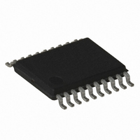
AT89LP2052-20XU Atmel, AT89LP2052-20XU Datasheet - Page 20

AT89LP2052-20XU
Manufacturer Part Number
AT89LP2052-20XU
Description
IC 8051 MCU FLASH 2K 20TSSOP
Manufacturer
Atmel
Series
89LPr
Datasheet
1.AT89LP2052-20PU.pdf
(94 pages)
Specifications of AT89LP2052-20XU
Core Processor
8051
Core Size
8-Bit
Speed
20MHz
Connectivity
SPI, UART/USART
Peripherals
Brown-out Detect/Reset, POR, PWM, WDT
Number Of I /o
15
Program Memory Size
2KB (2K x 8)
Program Memory Type
FLASH
Ram Size
256 x 8
Voltage - Supply (vcc/vdd)
2.4 V ~ 5.5 V
Oscillator Type
Internal
Operating Temperature
-40°C ~ 85°C
Package / Case
20-TSSOP
Processor Series
AT89x
Core
8051
Data Bus Width
8 bit
Data Ram Size
256 B
Interface Type
UART, SPI
Maximum Clock Frequency
20 MHz
Number Of Programmable I/os
15
Number Of Timers
2
Operating Supply Voltage
2.4 V to 5.5 V
Maximum Operating Temperature
+ 85 C
Mounting Style
SMD/SMT
3rd Party Development Tools
PK51, CA51, A51, ULINK2
Development Tools By Supplier
AT89ISP
Minimum Operating Temperature
- 40 C
Lead Free Status / RoHS Status
Lead free / RoHS Compliant
Eeprom Size
-
Data Converters
-
Lead Free Status / Rohs Status
Details
Table 14-4.
15. I/O Ports
15.1
20
Symbol
PCH
PSH
PT1H
PX1H
PT0H
PX0H
IPH = B7H
Not Bit Addressable
Bit
Quasi-bidirectional Output
AT89LP2052/LP4052
Function
Comparator Interrupt Priority High
Serial Port Interrupt Priority High
Timer 1 Interrupt Priority High
External Interrupt 1 Priority High
Timer 0 Interrupt Priority High
External Interrupt 0 Priority High
IPH
–
7
– Interrupt Priority High Register
All 15 port pins on the AT89LP2052/LP4052 may be configured to one of four modes: quasi-bidi-
rectional (standard 8051 port outputs), push-pull output, open-drain output, or input-only. Port
modes may be assigned in software on a pin-by-pin basis as shown in
default to input-only mode after reset. Each port pin also has a Schmitt-triggered input for
improved input noise rejection. During Power-down all the Schmitt-triggered inputs are disabled
with the exception of P3.2 and P3.3, which may be used to wake-up the device. Therefore P3.2
and P3.3 should not be left floating during Power-down.
Table 15-1.
Port pins in quasi-bidirectional output mode function similar to standard 8051 port pins. A Quasi-
bidirectional port can be used both as an input and output without the need to reconfigure the
port. This is possible because when the port outputs a logic high, it is weakly driven, allowing an
external device to pull the pin low. When the pin is driven low, it is driven strongly and able to
sink a large current. There are three pull-up transistors in the quasi-bidirectional output that
serve different purposes.
One of these pull-ups, called the “very weak” pull-up, is turned on whenever the port register for
the pin contains a logic “1”. This very weak pull-up sources a very small current that will pull the
pin high if it is left floating.
PCH
6
PxM0.y
0
0
1
1
Configuration Modes for Port x, Bit y
–
5
PxM1.y
0
1
0
1
PSH
4
Port Mode
Quasi-bidirectional
Push-pull Output
Input Only (High Impedance)
Open-Drain Output
PT1H
3
PX1H
2
Reset Value = X0X0 0000B
PT0H
1
Table
15-1. All port pins
3547J–MICRO–10/09
PX0H
0


