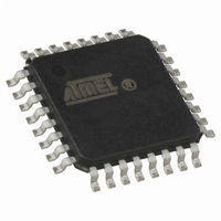
ATMEGA8A-AU Atmel, ATMEGA8A-AU Datasheet - Page 298

ATMEGA8A-AU
Manufacturer Part Number
ATMEGA8A-AU
Description
MCU AVR 8K FLASH 16MHZ 32-TQFP
Manufacturer
Atmel
Series
AVR® ATmegar
Specifications of ATMEGA8A-AU
Core Processor
AVR
Core Size
8-Bit
Speed
16MHz
Connectivity
I²C, SPI, UART/USART
Peripherals
Brown-out Detect/Reset, POR, PWM, WDT
Number Of I /o
23
Program Memory Size
8KB (4K x 16)
Program Memory Type
FLASH
Eeprom Size
512 x 8
Ram Size
1K x 8
Voltage - Supply (vcc/vdd)
2.7 V ~ 5.5 V
Data Converters
A/D 8x10b
Oscillator Type
Internal
Operating Temperature
-40°C ~ 85°C
Package / Case
32-TQFP, 32-VQFP
Processor Series
ATMEGA8x
Core
AVR8
Data Bus Width
8 bit
Data Ram Size
1 KB
Interface Type
SPI, TWI, USART
Maximum Clock Frequency
16 MHz
Number Of Programmable I/os
23
Number Of Timers
3
Maximum Operating Temperature
+ 85 C
Mounting Style
SMD/SMT
3rd Party Development Tools
EWAVR, EWAVR-BL
Development Tools By Supplier
ATAVRDRAGON, ATSTK500, ATSTK600, ATAVRISP2, ATAVRONEKIT
Minimum Operating Temperature
- 40 C
On-chip Adc
10 bit, 8 Channel
Controller Family/series
AVR MEGA
No. Of I/o's
23
Eeprom Memory Size
512Byte
Ram Memory Size
1KB
Cpu Speed
16MHz
Rohs Compliant
Yes
For Use With
ATSTK600 - DEV KIT FOR AVR/AVR32ATSTK500 - PROGRAMMER AVR STARTER KIT
Lead Free Status / RoHS Status
Lead free / RoHS Compliant
Available stocks
Company
Part Number
Manufacturer
Quantity
Price
Company:
Part Number:
ATMEGA8A-AU
Manufacturer:
NXP
Quantity:
1 001
Company:
Part Number:
ATMEGA8A-AU
Manufacturer:
ATM
Quantity:
10 000
Part Number:
ATMEGA8A-AU
Manufacturer:
ATMEL/爱特梅尔
Quantity:
20 000
31. Errata
31.1
8159D–AVR–02/11
ATmega8A, rev. L
The revision letter in this section refers to the revision of the ATmega8A device.
•
•
•
•
•
1. First Analog Comparator conversion may be delayed
2. Interrupts may be lost when writing the timer registers in the asynchronous timer
3. Signature may be Erased in Serial Programming Mode
4. CKOPT Does not Enable Internal Capacitors on XTALn/TOSCn Pins when 32kHz
First Analog Comparator conversion may be delayed
Interrupts may be lost when writing the timer registers in the asynchronous timer
Signature may be Erased in Serial Programming Mode
CKOPT Does not Enable Internal Capacitors on XTALn/TOSCn Pins when 32kHz Oscillator is
Used to Clock the Asynchronous Timer/Counter2
Reading EEPROM by using ST or STS to set EERE bit triggers unexpected interrupt request
If the device is powered by a slow rising V
take longer than expected on some devices.
Problem Fix / Workaround
When the device has been powered or reset, disable then enable theAnalog Comparator
before the first conversion.
The interrupt will be lost if a timer register that is synchronous timer clock is written when the
asynchronous Timer/Counter register (TCNTx) is 0x00.
Always check that the asynchronous Timer/Counter register neither have the value 0xFF nor
0x00 before writing to the asynchronous Timer Control Register (TCCRx), asynchronous
Timer Counter Register (TCNTx), or asynchronous Output Compare Register (OCRx).
If the signature bytes are read before a chiperase command is completed, the signature may
be erased causing the device ID and calibration bytes to disappear. This is critical, espe-
cially, if the part is running on internal RC oscillator.
Problem Fix / Workaround:
Ensure that the chiperase command has exceeded before applying the next command.
Oscillator is Used to Clock the Asynchronous Timer/Counter2
When the internal RC Oscillator is used as the main clock source, it is possible to run the
Timer/Counter2 asynchronously by connecting a 32kHz Oscillator between XTAL1/TOSC1
and XTAL2/TOSC2. But when the internal RC Oscillator is selected as the main clock
source, the CKOPT Fuse does not control the internal capacitors on XTAL1/TOSC1 and
XTAL2/TOSC2. As long as there are no capacitors connected to XTAL1/TOSC1 and
XTAL2/TOSC2, safe operation of the Oscillator is not guaranteed.
Problem Fix / Workaround
Use external capacitors in the range of 20 - 36 pF on XTAL1/TOSC1 and XTAL2/TOSC2.
This will be fixed in ATmega8A Rev. G where the CKOPT Fuse will control internal capaci-
tors also when internal RC Oscillator is selected as main clock source. For ATmega8A Rev.
G, CKOPT = 0 (programmed) will enable the internal capacitors on XTAL1 and XTAL2. Cus-
tomers who want compatibility between Rev. G and older revisions, must ensure that
CKOPT is unprogrammed (CKOPT = 1).
Problem Fix / Workaround
CC
, the first Analog Comparator conversion will
ATmega8A
298


