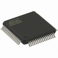
AT32UC3B0128-A2UT Atmel, AT32UC3B0128-A2UT Datasheet - Page 16

AT32UC3B0128-A2UT
Manufacturer Part Number
AT32UC3B0128-A2UT
Description
IC MCU AVR32 128KB FLASH 64-TQFP
Manufacturer
Atmel
Series
AVR®32 UC3r
Specifications of AT32UC3B0128-A2UT
Core Processor
AVR
Core Size
32-Bit
Speed
60MHz
Connectivity
I²C, IrDA, SPI, SSC, UART/USART, USB
Peripherals
Brown-out Detect/Reset, DMA, POR, PWM, WDT
Number Of I /o
44
Program Memory Size
128KB (128K x 8)
Program Memory Type
FLASH
Ram Size
32K x 8
Voltage - Supply (vcc/vdd)
1.65 V ~ 1.95 V
Data Converters
A/D 8x10b
Oscillator Type
Internal
Operating Temperature
-40°C ~ 85°C
Package / Case
64-TQFP, 64-VQFP
Processor Series
AT32UC3x
Core
AVR32
Data Bus Width
32 bit
Data Ram Size
32 KB
Interface Type
2-Wire, SPI, USART
Maximum Clock Frequency
60 MHz
Number Of Programmable I/os
44
Number Of Timers
3
Maximum Operating Temperature
+ 85 C
Mounting Style
SMD/SMT
3rd Party Development Tools
EWAVR32, EWAVR32-BL
Development Tools By Supplier
ATAVRDRAGON, ATSTK500, ATSTK600, ATAVRISP2, ATAVRONEKIT, ATEXTWIFI, ATEVK1101
Minimum Operating Temperature
- 40 C
On-chip Adc
10 bit, 8 Channel
Package
64TQFP
Device Core
AVR32
Family Name
AT32
Maximum Speed
60 MHz
Operating Supply Voltage
1.8|3.3 V
For Use With
ATAVRONEKIT - KIT AVR/AVR32 DEBUGGER/PROGRMMR770-1008 - ISP 4PORT ATMEL AVR32 MCU SPIATSTK600-TQFP64-2 - STK600 SOCKET/ADAPTER FOR 64-TQFATEVK1101 - KIT DEV/EVAL FOR AVR32 AT32UC3B
Lead Free Status / RoHS Status
Lead free / RoHS Compliant
Eeprom Size
-
Lead Free Status / Rohs Status
Details
Available stocks
Company
Part Number
Manufacturer
Quantity
Price
Company:
Part Number:
AT32UC3B0128-A2UT
Manufacturer:
XILINX
Quantity:
150
5.6.2.2
5.6.3
32059K–03/2011
Analog-to-Digital Converter (ADC) reference.
Dual Power Supply
Refer to
For decoupling recommendations for VDDIO, VDDANA, VDDCORE and VDDPLL, please refer
to the Schematic checklist.
In case of dual power supply, VDDIN and VDDOUT should be connected to ground to prevent
from leakage current.
To avoid over consumption during the power up sequence, VDDIO and VDDCORE voltage dif-
ference needs to stay in the range given
Figure 5-3.
The ADC reference (ADVREF) must be provided from an external source. Two decoupling
capacitors must be used to insure proper decoupling.
Figure 5-4.
Refer to
In case ADC is not used, the ADVREF pin should be connected to GND to avoid extra
consumption.
0.5
3.5
2.5
1.5
2
4
3
1
0
Section 9.3 on page 38
Section 9.4 on page 38
0
VDDIO versus VDDCORE during power up sequence
ADVREF Decoupling
Extra consumption on VDDIO
0.2
3.3V
0.4
C
VREF2
for decoupling capacitors values and regulator characteristics.
for decoupling capacitors values and electrical characteristics.
0.6
C
VREF1
Figure
0.8
VDDCORE (V)
5-3.
ADVREF
Extra consumption on VDDCORE
1
1.2
1.4
1.6
AT32UC3B
1.8
2
16


