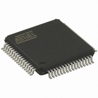
AT32UC3B0128-A2UT Atmel, AT32UC3B0128-A2UT Datasheet - Page 81

AT32UC3B0128-A2UT
Manufacturer Part Number
AT32UC3B0128-A2UT
Description
IC MCU AVR32 128KB FLASH 64-TQFP
Manufacturer
Atmel
Series
AVR®32 UC3r
Specifications of AT32UC3B0128-A2UT
Core Processor
AVR
Core Size
32-Bit
Speed
60MHz
Connectivity
I²C, IrDA, SPI, SSC, UART/USART, USB
Peripherals
Brown-out Detect/Reset, DMA, POR, PWM, WDT
Number Of I /o
44
Program Memory Size
128KB (128K x 8)
Program Memory Type
FLASH
Ram Size
32K x 8
Voltage - Supply (vcc/vdd)
1.65 V ~ 1.95 V
Data Converters
A/D 8x10b
Oscillator Type
Internal
Operating Temperature
-40°C ~ 85°C
Package / Case
64-TQFP, 64-VQFP
Processor Series
AT32UC3x
Core
AVR32
Data Bus Width
32 bit
Data Ram Size
32 KB
Interface Type
2-Wire, SPI, USART
Maximum Clock Frequency
60 MHz
Number Of Programmable I/os
44
Number Of Timers
3
Maximum Operating Temperature
+ 85 C
Mounting Style
SMD/SMT
3rd Party Development Tools
EWAVR32, EWAVR32-BL
Development Tools By Supplier
ATAVRDRAGON, ATSTK500, ATSTK600, ATAVRISP2, ATAVRONEKIT, ATEXTWIFI, ATEVK1101
Minimum Operating Temperature
- 40 C
On-chip Adc
10 bit, 8 Channel
Package
64TQFP
Device Core
AVR32
Family Name
AT32
Maximum Speed
60 MHz
Operating Supply Voltage
1.8|3.3 V
For Use With
ATAVRONEKIT - KIT AVR/AVR32 DEBUGGER/PROGRMMR770-1008 - ISP 4PORT ATMEL AVR32 MCU SPIATSTK600-TQFP64-2 - STK600 SOCKET/ADAPTER FOR 64-TQFATEVK1101 - KIT DEV/EVAL FOR AVR32 AT32UC3B
Lead Free Status / RoHS Status
Lead free / RoHS Compliant
Eeprom Size
-
Lead Free Status / Rohs Status
Details
Available stocks
Company
Part Number
Manufacturer
Quantity
Price
Company:
Part Number:
AT32UC3B0128-A2UT
Manufacturer:
XILINX
Quantity:
150
32059K–03/2011
- Power Manager
4. SPI disable does not work in SLAVE mode
5. SPI data transfer hangs with CSR0.CSAAT==1 and MR.MODFDIS==0
6. Disabling SPI has no effect on flag TDRE flag
1. If the BOD level is higher than VDDCORE, the part is constantly resetted
2. When the main clock is RCSYS, TIMER_CLOCK5 is equal to PBA clock
2. Clock sources will not be stopped in STATIC sleep mode if the difference between
3. Increased Power Consunption in VDDIO in sleep modes
SPI disable does not work in SLAVE mode.
Fix/Workaround
Read the last received data, then perform a Software Reset.
When CSR0.CSAAT==1 and mode fault detection is enabled (MR.MODFDIS==0), the SPI
module will not start a data transfer.
Fix/Workaround
Disable mode fault detection by writing a one to MR.MODFDIS.
Disabling SPI has no effect on TDRE whereas the write data command is filtered when SPI
is disabled. This means that as soon as the SPI is disabled it becomes impossible to reset
the TDRE flag by writing in the TDR. So if the SPI is disabled during a PDCA transfer, the
PDCA will continue to write data in the TDR (as TDRE stays high) until its buffer is empty,
and all data written after the disable command is lost.
Fix/Workaround
Disable the PDCA, insert 2 NOPs, disable SPI. To continue the transfer: Enable SPI, enable
PDCA.
If the BOD level is set to a value higher than VDDCORE and enabled by fuses, the part will
be in constant reset.
Fix/Workaround
Apply an external voltage on VDDCORE that is higher than the BOD level and is lower than
VDDCORE max and disable the BOD.
When the main clock is generated from RCSYS, TIMER_CLOCK5 is equal to PBA Clock
and not PBA Clock / 128.
Fix/Workaround
None.
CPU and PBx division factor is too high
If the division factor between the CPU/HSB and PBx frequencies is more than 4 when going
to a sleep mode where the system RC oscillator is turned off, then high speed clock sources
will not be turned off. This will result in a significantly higher power consumption during the
sleep mode.
Fix/Workaround
Before going to sleep modes where the system RC oscillator is stopped, make sure that the
factor between the CPU/HSB and PBx frequencies is less than or equal to 4.
If the OSC0 is enabled in crystal mode when entering a sleep mode where the OSC0 is dis-
abled, this will lead to an increased power consumption in VDDIO.
Fix/Workaround
Disable the OSC0 through the System Control Interface (SCIF) before going to any sleep
mode where the OSC0 is disabled, or pull down or up XIN0 and XOUT0 with 1 Mohm
resistor.
AT32UC3B
81


