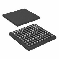
ATSAM3S1CA-CU Atmel, ATSAM3S1CA-CU Datasheet - Page 33

ATSAM3S1CA-CU
Manufacturer Part Number
ATSAM3S1CA-CU
Description
IC MCU 32BIT 64KB FLASH 100BGA
Manufacturer
Atmel
Series
SAM3Sr
Specifications of ATSAM3S1CA-CU
Core Processor
ARM® Cortex-M3™
Core Size
32-Bit
Speed
64MHz
Connectivity
EBI/EMI, I²C, MMC, SPI, SSC, UART/USART, USB
Peripherals
Brown-out Detect/Reset, DMA, I²S, POR, PWM, WDT
Number Of I /o
79
Program Memory Size
64KB (64K x 8)
Program Memory Type
FLASH
Ram Size
16K x 8
Voltage - Supply (vcc/vdd)
1.62 V ~ 1.95 V
Data Converters
A/D 16x10/12b, D/A 2x12b
Oscillator Type
Internal
Operating Temperature
-40°C ~ 85°C
Package / Case
100-LFBGA
Processor Series
ATSAM3x
Core
ARM Cortex M3
3rd Party Development Tools
JTRACE-CM3, MDK-ARM, RL-ARM, ULINK2
Development Tools By Supplier
ATSAM3S-EK
Lead Free Status / RoHS Status
Lead free / RoHS Compliant
Eeprom Size
-
Lead Free Status / Rohs Status
Details
Available stocks
Company
Part Number
Manufacturer
Quantity
Price
9.1.3.9
9.1.3.10
9.1.3.11
9.1.4
9.2
9.2.1
6500CS–ATARM–24-Jan-11
External Memories
Boot Strategies
Static Memory Controller
Fast Flash Programming Interface
SAM-BA
GPNVM Bits
®
Boot
The Fast Flash Programming Interface allows programming the device through either a serial
JTAG interface or through a multiplexed fully-handshaked parallel port. It allows gang program-
ming with market-standard industrial programmers.
The FFPI supports read, page program, page erase, full erase, lock, unlock and protect
commands.
The Fast Flash Programming Interface is enabled and the Fast Programming Mode is entered
when TST and PA0 and PA1are tied low.
The SAM-BA Boot is a default Boot Program which provides an easy way to program in-situ the
on-chip Flash memory.
The SAM-BA Boot Assistant supports serial communication via the UART and USB.
The SAM-BA Boot provides an interface with SAM-BA Graphic User Interface (GUI).
The SAM3S features two GPNVM bits that can be cleared or set respectively through the com-
mands “Clear GPNVM Bit” and “Set GPNVM Bit” of the EEFC User Interface.
Table 9-2.
The system always boots at address 0x0. To ensure maximum boot possibilities, the memory
layout can be changed via GPNVM.
A general-purpose NVM (GPNVM) bit is used to boot either on the ROM (default) or from the
Flash.
The GPNVM bit can be cleared or set respectively through the commands “Clear General-pur-
pose NVM Bit” and “Set General-purpose NVM Bit” of the EEFC User Interface.
Setting GPNVM Bit 1 selects the boot from the Flash, clearing it selects the boot from the ROM.
Asserting ERASE clears the GPNVM Bit 1 and thus selects the boot from the ROM by default.
The SAM3S features an External Bus Interface to provide the interface to a wide range of exter-
nal memories and to any parallel peripheral.
• 8-bit Data Bus
• Up to 24-bit Address Bus (up to 16 MBytes linear per chip select)
• Up to 4 chip selects, Configurable Assignment
• Multiple Access Modes supported
GPNVMBit[#]
– Chip Select, Write enable or Read enable Control Mode
0
1
General Purpose Non-volatile Memory Bits
Function
Security bit
Boot mode selection
SAM3S Summary
33


