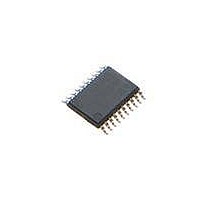
STM8L101F2P6 STMicroelectronics, STM8L101F2P6 Datasheet - Page 22

STM8L101F2P6
Manufacturer Part Number
STM8L101F2P6
Description
MCU 8BIT 4K FLASH 20TSSOP
Manufacturer
STMicroelectronics
Series
STM8L EnergyLiter
Datasheet
1.STM8L101-EVAL.pdf
(81 pages)
Specifications of STM8L101F2P6
Core Processor
STM8
Core Size
8-Bit
Speed
16MHz
Connectivity
I²C, SPI, UART/USART
Peripherals
Infrared, POR, PWM, WDT
Number Of I /o
18
Program Memory Size
4KB (4K x 8)
Program Memory Type
FLASH
Ram Size
1.5K x 8
Voltage - Supply (vcc/vdd)
1.65 V ~ 3.6 V
Oscillator Type
Internal
Operating Temperature
-40°C ~ 85°C
Package / Case
20-TSSOP
Processor Series
STM8L10x
Core
STM8
Data Bus Width
8 bit
Data Ram Size
1.5 KB
Interface Type
I2C, SPI, USART
Maximum Clock Frequency
16 MHz
Number Of Programmable I/os
18
Number Of Timers
3
Operating Supply Voltage
1.65 V to 3.6 V
Maximum Operating Temperature
+ 85 C
Mounting Style
SMD/SMT
3rd Party Development Tools
EWSTM8
Development Tools By Supplier
STX-RLINK
Minimum Operating Temperature
- 40 C
Featured Product
STM32 Cortex-M3 Companion Products
Eeprom Size
-
Data Converters
-
Lead Free Status / RoHS Status
Lead free / RoHS Compliant
Eeprom Size
-
Data Converters
-
Lead Free Status / Rohs Status
Lead free / RoHS Compliant
Available stocks
Company
Part Number
Manufacturer
Quantity
Price
Part Number:
STM8L101F2P6
Manufacturer:
ST
Quantity:
20 000
Pin description
Table 4.
1. Please refer to the warning below.
2. At power-up, the PA1/NRST pin is a reset input pin with pull-up. To be used as a general purpose pin (PA1), it can be
3. A pull-up is applied to PB0 and PB4 during the reset phase. These two pins are input floating after reset release.
4. In the open-drain output column, ‘T’ defines a true open-drain I/O (P-buffer and protection diode to V
5. The PA0 pin is in input pull-up during the reset phase and after reset release.
6. High sink LED driver capability available on PA0.
22/81
-
20 20 3
configured only as output open-drain or push-pull, not as a general purpose input. Refer to Section Configuring NRST/PA1
pin as general purpose output in the STM8L101xx reference manual (RM0013).
implemented).
-
Pin number
-
27 27 31 PC6
28 28 32
STM8L101xx pin description (continued)
Warning:
PA0
BEEP/IR_TIM
(5)
Pin name
/SWIM/
For the STM8L101F1U6ATR, STM8L101F2U6ATR,
STM8L101F3U6ATR, STM8L101G2U6ATR and
STM8L101G3U6ATR part numbers (devices with COMP_REF
pin), all ports available on 32-pin packages must be
considered as active ports. To avoid spurious effects, you
have to configure them as input pull-up. A small increase in
consumption (typ. < 300 µA) may occur during the power up
and reset phase until these ports are properly configured.
(6)
I/O X
I/O X
Doc ID 15275 Rev 11
Input
X
X
(5)
X
X
HS
HS
(6)
Output
X
X
X
X
Port C6
Port A0
DD
SWIM input and out-
put /Beep out-
put/Timer Infrared
output
Alternate function
are not
STM8L101xx


