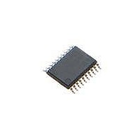
STM8L101F2P6 STMicroelectronics, STM8L101F2P6 Datasheet - Page 64

STM8L101F2P6
Manufacturer Part Number
STM8L101F2P6
Description
MCU 8BIT 4K FLASH 20TSSOP
Manufacturer
STMicroelectronics
Series
STM8L EnergyLiter
Datasheet
1.STM8L101-EVAL.pdf
(81 pages)
Specifications of STM8L101F2P6
Core Processor
STM8
Core Size
8-Bit
Speed
16MHz
Connectivity
I²C, SPI, UART/USART
Peripherals
Infrared, POR, PWM, WDT
Number Of I /o
18
Program Memory Size
4KB (4K x 8)
Program Memory Type
FLASH
Ram Size
1.5K x 8
Voltage - Supply (vcc/vdd)
1.65 V ~ 3.6 V
Oscillator Type
Internal
Operating Temperature
-40°C ~ 85°C
Package / Case
20-TSSOP
Processor Series
STM8L10x
Core
STM8
Data Bus Width
8 bit
Data Ram Size
1.5 KB
Interface Type
I2C, SPI, USART
Maximum Clock Frequency
16 MHz
Number Of Programmable I/os
18
Number Of Timers
3
Operating Supply Voltage
1.65 V to 3.6 V
Maximum Operating Temperature
+ 85 C
Mounting Style
SMD/SMT
3rd Party Development Tools
EWSTM8
Development Tools By Supplier
STX-RLINK
Minimum Operating Temperature
- 40 C
Featured Product
STM32 Cortex-M3 Companion Products
Eeprom Size
-
Data Converters
-
Lead Free Status / RoHS Status
Lead free / RoHS Compliant
Eeprom Size
-
Data Converters
-
Lead Free Status / Rohs Status
Lead free / RoHS Compliant
Available stocks
Company
Part Number
Manufacturer
Quantity
Price
Part Number:
STM8L101F2P6
Manufacturer:
ST
Quantity:
20 000
Electrical parameters
9.4
64/81
Static latch-up
●
Table 37.
Thermal characteristics
The maximum chip junction temperature (T
Table 16: General operating conditions on page
The maximum chip-junction temperature, T
using the following equation:
T
Where:
●
●
●
●
●
Jmax
LU: 2 complementary static tests are required on 10 parts to assess the latch-up
performance. A supply overvoltage (applied to each power supply pin) and a current
injection (applied to each input, output and configurable I/O pin) are performed on each
sample. This test conforms to the EIA/JESD 78 IC latch-up standard. For more details,
refer to the application note AN1181.
T
P
P
internal power.
P
where:
P
taking into account the actual V
the application.
Amax
JA
= T
Dmax
INTmax
I/Omax
I/Omax
Symbol
is the package junction-to-ambient thermal resistance in C/W
LU
Amax
is the maximum ambient temperature in C
is the sum of P
=
represents the maximum power dissipation on output pins
Electrical sensitivities
is the product of I
+ (P
(V
OL
Dmax
*I
Static latch-up class
OL
x
) + ((V
INTmax
JA
)
Doc ID 15275 Rev 11
DD
DD
and P
and V
-V
OL
Parameter
OH)
/I
I/Omax
DD
OL and
*I
, expressed in watts. This is the maximum chip
OH
Jmax
Jmax
),
(P
V
) must never exceed the values given in
, in degrees Celsius, may be calculated
OH
40.
Dmax
/I
OH
= P
of the I/Os at low and high level in
INTmax
+ P
I/Omax
)
Class
II
STM8L101xx


