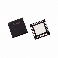
C8051F311-GMR Silicon Laboratories Inc, C8051F311-GMR Datasheet - Page 215

C8051F311-GMR
Manufacturer Part Number
C8051F311-GMR
Description
IC 8051 MCU 16K FLASH 28MLP
Manufacturer
Silicon Laboratories Inc
Series
C8051F31xr
Specifications of C8051F311-GMR
Core Processor
8051
Core Size
8-Bit
Speed
25MHz
Connectivity
SMBus (2-Wire/I²C), SPI, UART/USART
Peripherals
POR, PWM, Temp Sensor, WDT
Number Of I /o
25
Program Memory Size
16KB (16K x 8)
Program Memory Type
FLASH
Ram Size
1.25K x 8
Voltage - Supply (vcc/vdd)
2.7 V ~ 3.6 V
Data Converters
A/D 17x10b
Oscillator Type
Internal
Operating Temperature
-40°C ~ 85°C
Package / Case
28-VQFN Exposed Pad, 28-HVQFN, 28-SQFN, 28-DHVQFN
Package
24QFN EP
Device Core
8051
Family Name
C8051F31x
Maximum Speed
25 MHz
Operating Supply Voltage
3.3 V
Data Bus Width
8 Bit
Number Of Programmable I/os
25
Interface Type
I2C/SMBus/SPI/UART
On-chip Adc
17-chx10-bit
Number Of Timers
4
For Use With
336-1446 - ADAPTER PROGRAM TOOLSTICK F311336-1253 - DEV KIT FOR C8051F310/F311
Lead Free Status / RoHS Status
Lead free / RoHS Compliant
Eeprom Size
-
Available stocks
Company
Part Number
Manufacturer
Quantity
Price
Part Number:
C8051F311-GMR
Manufacturer:
SILICON LABS/芯科
Quantity:
20 000
18.4. Register Descriptions for PCA
Following are detailed descriptions of the special function registers related to the operation of the PCA.
Bit7:
Bit6:
Bit5:
Bit4:
Bit3:
Bit2:
Bit1:
Bit0:
R/W
CF
Bit7
CF: PCA Counter/Timer Overflow Flag.
Set by hardware when the PCA Counter/Timer overflows from 0xFFFF to 0x0000. When the
Counter/Timer Overflow (CF) interrupt is enabled, setting this bit causes the CPU to vector
to the PCA interrupt service routine. This bit is not automatically cleared by hardware and
must be cleared by software.
CR: PCA Counter/Timer Run Control.
This bit enables/disables the PCA Counter/Timer.
0: PCA Counter/Timer disabled.
1: PCA Counter/Timer enabled.
UNUSED. Read = 0b, Write = don't care.
CCF4: PCA Module 4 Capture/Compare Flag.
This bit is set by hardware when a match or capture occurs. When the CCF4 interrupt is
enabled, setting this bit causes the CPU to vector to the PCA interrupt service routine. This
bit is not automatically cleared by hardware and must be cleared by software.
CCF3: PCA Module 3 Capture/Compare Flag.
This bit is set by hardware when a match or capture occurs. When the CCF3 interrupt is
enabled, setting this bit causes the CPU to vector to the PCA interrupt service routine. This
bit is not automatically cleared by hardware and must be cleared by software.
CCF2: PCA Module 2 Capture/Compare Flag.
This bit is set by hardware when a match or capture occurs. When the CCF2 interrupt is
enabled, setting this bit causes the CPU to vector to the PCA interrupt service routine. This
bit is not automatically cleared by hardware and must be cleared by software.
CCF1: PCA Module 1 Capture/Compare Flag.
This bit is set by hardware when a match or capture occurs. When the CCF1 interrupt is
enabled, setting this bit causes the CPU to vector to the PCA interrupt service routine. This
bit is not automatically cleared by hardware and must be cleared by software.
CCF0: PCA Module 0 Capture/Compare Flag.
This bit is set by hardware when a match or capture occurs. When the CCF0 interrupt is
enabled, setting this bit causes the CPU to vector to the PCA interrupt service routine. This
bit is not automatically cleared by hardware and must be cleared by software.
R/W
CR
Bit6
SFR Definition 18.1. PCA0CN: PCA Control
R/W
Bit5
CCF4
R/W
Bit4
Rev. 1.7
CCF3
R/W
Bit3
C8051F310/1/2/3/4/5/6/7
CCF2
R/W
Bit2
CCF1
R/W
Bit1
(bit addressable)
CCF0
R/W
Bit0
SFR Address:
00000000
Reset Value
0xD8
215


