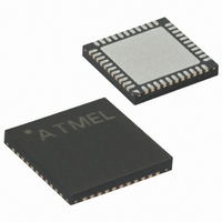
ATMEGA162V-1MC Atmel, ATMEGA162V-1MC Datasheet - Page 133

ATMEGA162V-1MC
Manufacturer Part Number
ATMEGA162V-1MC
Description
IC MCU AVR 16K 1.8V 8MHZ 44-QFN
Manufacturer
Atmel
Series
AVR® ATmegar
Specifications of ATMEGA162V-1MC
Core Processor
AVR
Core Size
8-Bit
Speed
1MHz
Connectivity
EBI/EMI, SPI, UART/USART
Peripherals
Brown-out Detect/Reset, POR, PWM, WDT
Number Of I /o
35
Program Memory Size
16KB (8K x 16)
Program Memory Type
FLASH
Eeprom Size
512 x 8
Ram Size
1K x 8
Voltage - Supply (vcc/vdd)
1.8 V ~ 3.6 V
Oscillator Type
Internal
Operating Temperature
0°C ~ 70°C
Package / Case
44-VQFN Exposed Pad
Lead Free Status / RoHS Status
Contains lead / RoHS non-compliant
Data Converters
-
- Current page: 133 of 289
- Download datasheet (3Mb)
Extended Timer/Counter
Interrupt Mask Register –
ETIMSK
2513C–AVR–09/02
(1)
• Bit 5 – OCIE1B: Timer/Counter1, Output Compare B Match Interrupt Enable
When this bit is written to one, and the I-flag in the Status Register is set (interrupts glo-
bally enabled), the Timer/Counter1 Output Compare B Match interrupt is enabled. The
corresponding Interrupt Vector (See “Interrupts” on page 55.) is executed when the
OCF1B flag, located in TIFR, is set.
• Bit 3 – TICIE1: Timer/Counter1, Input Capture Interrupt Enable
When this bit is written to one, and the I-flag in the Status Register is set (interrupts glo-
bally enabled), the Timer/Counter1 Input Capture interrupt is enabled. The
corresponding Interrupt Vector (See “Interrupts” on page 55.) is executed when the
ICF1 flag, located in TIFR, is set.
Note:
• Bit 5 – TICIE3: Timer/Counter3, Input Capture Interrupt Enable
When this bit is written to one, and the I-flag in the Status Register is set (interrupts glo-
bally enabled), the Timer/Counter3 Input Capture interrupt is enabled. The
corresponding Interrupt Vector (See “Interrupts” on page 55.) is executed when the
ICF3 flag, located in TIFR, is set.
• Bit 4 – OCIE3A: Timer/Counter3, Output Compare A Match Interrupt Enable
When this bit is written to one, and the I-flag in the Status Register is set (interrupts glo-
bally enabled), the Timer/Counter3 Output Compare A Match interrupt is enabled. The
corresponding Interrupt Vector (See “Interrupts” on page 55.) is executed when the
OCF3A flag, located in TIFR, is set.
• Bit 3 – OCIE3B: Timer/Counter3, Output Compare B Match Interrupt Enable
When this bit is written to one, and the I-flag in the Status Register is set (interrupts glo-
bally enabled), the Timer/Counter3 Output Compare B Match interrupt is enabled. The
corresponding Interrupt Vector (See “Interrupts” on page 55.) is executed when the
OCF3B flag, located in TIFR, is set.
• Bit 2 – TOIE3: Timer/Counter3, Overflow Interrupt Enable
When this bit is written to one, and the I-flag in the Status Register is set (interrupts glo-
bally enabled), the Timer/Counter3 overflow interrupt is enabled. The corresponding
Interrupt Vector (See “Interrupts” on page 55.) is executed when the TOV3 flag, located
in TIFR, is set.
Bit
Read/Write
Initial Value
1. This register contains interrupt control bits for several Timer/Counters, but only
Timer3 bits are described in this section. The remaining bits are described in their
respective Timer sections.
R
7
0
6
R
0
TICIE3
R/W
5
0
OCIE3A
R/W
4
0
OCIE3B
R/W
3
0
ATmega162(V/U/L)
TOIE3
R/W
2
0
R
1
–
0
R
0
–
0
ETIMSK
133
Related parts for ATMEGA162V-1MC
Image
Part Number
Description
Manufacturer
Datasheet
Request
R

Part Number:
Description:
Manufacturer:
Atmel Corporation
Datasheet:

Part Number:
Description:
IC AVR MCU 16K 16MHZ 5V 44TQFP
Manufacturer:
Atmel
Datasheet:

Part Number:
Description:
IC AVR MCU 16K 16MHZ 5V 40DIP
Manufacturer:
Atmel
Datasheet:

Part Number:
Description:
IC AVR MCU 16K 16MHZ 5V 44-QFN
Manufacturer:
Atmel
Datasheet:

Part Number:
Description:
IC MCU AVR 16K 5V 16MHZ 44-TQFP
Manufacturer:
Atmel
Datasheet:

Part Number:
Description:
IC MCU AVR 16K 5V 16MHZ 44-QFN
Manufacturer:
Atmel
Datasheet:

Part Number:
Description:
MCU AVR 16KB FLASH 16MHZ 44QFN
Manufacturer:
Atmel
Datasheet:

Part Number:
Description:
MCU AVR 16KB FLASH 16MHZ 44TQFP
Manufacturer:
Atmel
Datasheet:

Part Number:
Description:
IC MCU AVR 16K 5V 16MHZ 44-TQFP
Manufacturer:
Atmel
Datasheet:

Part Number:
Description:
IC MCU AVR 16K 5V 16MHZ 44-QFN
Manufacturer:
Atmel
Datasheet:

Part Number:
Description:
IC MCU AVR 16K 5V 16MHZ 40-DIP
Manufacturer:
Atmel
Datasheet:

Part Number:
Description:
IC MCU AVR 16K 5V 16MHZ 40-DIP
Manufacturer:
Atmel
Datasheet:

Part Number:
Description:
IC MCU AVR 16K 5V 16MHZ 44-TQFP
Manufacturer:
Atmel
Datasheet:


