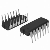
LM2902NG ON Semiconductor, LM2902NG Datasheet - Page 6

LM2902NG
Manufacturer Part Number
LM2902NG
Description
IC OPAMP QUAD SGL SUPPLY 14DIP
Manufacturer
ON Semiconductor
Specifications of LM2902NG
Amplifier Type
General Purpose
Number Of Circuits
4
Slew Rate
0.6 V/µs
Gain Bandwidth Product
1MHz
Current - Input Bias
90nA
Voltage - Input Offset
2000µV
Current - Supply
1.4mA
Current - Output / Channel
40mA
Voltage - Supply, Single/dual (±)
3 V ~ 32 V, ±1.5 V ~ 16 V
Operating Temperature
-40°C ~ 105°C
Mounting Type
Through Hole
Package / Case
14-DIP (0.300", 7.62mm)
Number Of Channels
4
Common Mode Rejection Ratio (min)
50 dB
Input Voltage Range (max)
Positive Rail - 5.7 V
Input Voltage Range (min)
Negative Rail
Input Offset Voltage
7 mV
Input Bias Current (max)
250 nA
Output Current (typ)
40 mA
Operating Supply Voltage
32 V
Supply Current
1.2 mA
Maximum Operating Temperature
+ 105 C
Minimum Operating Temperature
- 40 C
Dual Supply Voltage
+/- 3 V, +/- 5 V, +/- 9 V
Maximum Dual Supply Voltage
+/- 16 V
Minimum Dual Supply Voltage
+/- 1.5 V
Mounting Style
Through Hole
Shutdown
No
Supply Voltage (max)
32 V
Supply Voltage (min)
3 V
Technology
Bipolar
Voltage Gain Db
100 dB
Bandwidth
1 MHz
Channel Separation
-120
Common Mode Rejection Ratio
70
Current, Input Bias
-500 nA
Current, Input Offset
200 nA
Current, Output
40 mA
Current, Supply
3 mA
Number Of Amplifiers
Quad
Package Type
PDIP-14
Temperature, Operating, Range
-40 to +105 °C
Voltage, Gain
15 V/mV
Voltage, Input
-0.3 to 32 VDC
Voltage, Offset
10 mV
Voltage, Output, High
3.5 V
Voltage, Output, Low
5 mV
Voltage, Supply
3 to 32 VDC
Lead Free Status / RoHS Status
Lead free / RoHS Compliant
Output Type
-
-3db Bandwidth
-
Lead Free Status / Rohs Status
Lead free / RoHS Compliant
Other names
LM2902NGOS
compensated, two−stage operational amplifiers. The first
stage of each consists of differential input devices Q20 and
Q18 with input buffer transistors Q21 and Q17 and the
differential to single ended converter Q3 and Q4. The first
stage performs not only the first stage gain function but also
performs the level shifting and transconductance reduction
functions. By reducing the transconductance, a smaller
compensation capacitor (only 5.0 pF) can be employed, thus
saving chip area. The transconductance reduction is
accomplished by splitting the collectors of Q20 and Q18.
Another feature of this input stage is that the input common
mode range can include the negative supply or ground, in
single supply operation, without saturating either the input
devices or the differential to single−ended converter. The
second stage consists of a standard current source load
amplifier stage.
The LM324 series is made using four internally
3.0 V to V
Single Supply
CC(max)
70
60
50
40
30
20
10
0
1.0
1
2
3
4
V
V
CC
EE
/GND
Figure 4. Gain and Phase Margin
10
CIRCUIT DESCRIPTION
Gain Margin
LOAD CAPACITANCE (pF)
http://onsemi.com
Figure 3.
100
6
regulator which has a low temperature coefficient thus
giving each amplifier good temperature characteristics as
well as excellent power supply rejection.
Each amplifier is biased from an internal−voltage
Figure 2. Large Signal Voltage Follower Response
Phase Margin
1000
V
V
CC
EE
10000
1
2
3
4
70
60
50
0
40
30
20
10
Split Supplies
5.0 ms/DIV
1.5 V to V
1.5 V to V
V
R
T
CC(max)
EE(max)
A
CC
L
= 25°C
= 2.0 kW
= 15 Vdc


