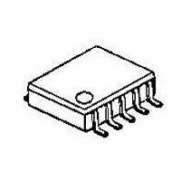
NJM2140R-TE1 NJR, NJM2140R-TE1 Datasheet - Page 2

NJM2140R-TE1
Manufacturer Part Number
NJM2140R-TE1
Description
IC OPAMP DUAL LOW-SATURAT 8-VSP
Manufacturer
NJR
Datasheet
1.NJM2140R-TE1.pdf
(5 pages)
Specifications of NJM2140R-TE1
Amplifier Type
General Purpose
Number Of Circuits
2
Slew Rate
4 V/µs
Gain Bandwidth Product
12MHz
Current - Input Bias
100nA
Voltage - Input Offset
1000µV
Current - Supply
3.5mA
Voltage - Supply, Single/dual (±)
±1 V ~ 7 V
Operating Temperature
-20°C ~ 75°C
Mounting Type
Surface Mount
Package / Case
8-VSP
Number Of Channels
2
Voltage Gain Db
80 dB
Common Mode Rejection Ratio (min)
60 dB
Input Offset Voltage
6 mV
Supply Current
5 mA
Maximum Power Dissipation
320 mW
Maximum Operating Temperature
+ 75 C
Mounting Style
SMD/SMT
Maximum Dual Supply Voltage
+/- 7 V
Minimum Operating Temperature
- 20 C
Lead Free Status / RoHS Status
Contains lead / RoHS non-compliant
Output Type
-
Current - Output / Channel
-
-3db Bandwidth
-
Lead Free Status / Rohs Status
Details
■ ABSOLUTE MAXIMUM RATINGS
Supply Voltage
Differential Input Voltage
Power Dissipation
Operating Temperature Range
Storage Temperature Range
■ ELECTRICAL CHARACTERISTICS
Input Offset Voltage
Input Offset Current
Input Bias Current
Large Signal Voltage Gain
Maximum Output Voltage Swings 1
Maximum Output Voltage Swings 2
Input Common Mode Voltage Range
Common Mode Rejection Ratio
Supply Voltage Rejection Ratio
Operating Current
Slew Rate
Unity Gain Frequency
- 2 -
PARAMETER
PARAMETER
SYMBOL
SYMBOL
CMRR
PSRR
V
V
V
V
T
T
V
SR
V
I
P
A
I
+
I
OM1
OM2
CC
f
IO
ICM
opr
stg
B
T
/V
IO
ID
D
V
-
R
R
R
R
S
L
L
L
≥10kΩ
=2.5kΩ
≥10kΩ
≤
10kΩ
TEST CONDITION
( R/RB1 ) 320
RATINGS
-40~+125
-20~+75
± 7.0
± 14
( Ta=25˚C )
UNIT
± 2.0
± 2.3
± 1.5
MIN.
mW
˚C
˚C
60
60
60
V
V
-
-
-
-
-
-
TYP.
± 2.2
± 2.4
100
3.5
10
80
74
80
12
4
1
-
( V
+
/V
-
MAX.
=2.5V
300
20
6
5
-
-
-
-
-
-
-
-
Ver.2003-03-19
,
Ta=25˚C )
UNIT
MHz
V/µs
mV
mA
nA
nA
dB
dB
dB
V
V
V


