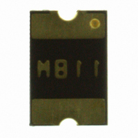
MF-MSMF110/16-2 Bourns Inc., MF-MSMF110/16-2 Datasheet - Page 3

MF-MSMF110/16-2
Manufacturer Part Number
MF-MSMF110/16-2
Description
PTC RESETTABLE 1.10A 16V 1812
Manufacturer
Bourns Inc.
Series
MF-MSMFr
Type
PTC Resettable Fusesr
Specifications of MF-MSMF110/16-2
Package / Case
1812 (4532 Metric)
R Min/max
0.040 ~ 0.210 Ohm
Voltage - Max
16V
Time To Trip
0.3s
Current - Hold (ih) (max)
1.1A
Current - Trip (it)
2.2A
Current - Max
100A
Hold Current
1.1 Amps
Trip Current
2.2 Amps
Current Rating (max)
100 Amps
Resistance
0.21 Ohms
Maximum Voltage
16 VoltsDC
Termination Style
SMD/SMT
Mounting Style
SMD/SMT
Current Rating
100 Amps
Dimensions
4.73 mm L x 3.41 mm W x 0.75 mm H
Operating Temperature Range
- 40 C to + 85 C
Brand/series
MF-MSMF Series
Current, Rating
100 A
Mounting Type
PCB
Primary Type
Resettable
Resistance, Dc
0.04 Ohms
Size
4532
Termination
SMT
Voltage, Rating
16 VDC
Holding Current
1.1A
Tripping Current
2.2A
Initial Resistance Max
0.21ohm
Operating Voltage
16V
Ptc Fuse Case
1812
External Depth
0.6mm
Initial Resistance Min
0.04ohm
Rohs Compliant
Yes
Lead Free Status / RoHS Status
Lead free / RoHS Compliant
Lead Free Status / RoHS Status
Lead free / RoHS Compliant, Lead free / RoHS Compliant
Other names
MF-MSMF110/16-2TR
Available stocks
Company
Part Number
Manufacturer
Quantity
Price
Company:
Part Number:
MF-MSMF110/16-2
Manufacturer:
BOURNS
Quantity:
60 000
Company:
Part Number:
MF-MSMF110/16-2
Manufacturer:
Bourns Inc.
Quantity:
35 206
Specifi cations are subject to change without notice.
Customers should verify actual device performance in their specifi c applications.
Style 1
Style 2
Product Dimensions (see previous page for dimensions)
Typical Time to Trip at 23 ˚C
Top and Bottom View
MF-MSMF Series - PTC Resettable Fuses
Top View
MF-MSMF010
0.001
8
C
0.01
A
100
0.1
10
1
0.1
MF-MSMF030
D
B
D
Side View
C
Bottom View
A
1
Fault Current (Amps)
Recommended Pad Layout
(.059 ± .002)
1.5 ± 0.05
MF-MSMF014
(.106 ± .004)
B
2.7 ± 0.1
MF-MSMF020
MF-MSMF075/24
Side View
MF-MSMF050
(.066 ± .002)
1.68 ± 0.05
MF-MSMF200
C
10
(0.126 ± .004)
Recommended Pad Layout
MF-MSMF260
3.2 ± 0.1
(.059 ± .002)
1.5 ± 0.05
MF-MSMF160
MF-MSMF110
MF-MSMF075
MF-MSMF150
MF-MSMF110/16
MF-MSMF125
100
(.122 ± .004)
3.1 ± 0.10
(.114 ± .004)
2.95 ± 0.10
Terminal material:
Termination pad solderability:
Recommended Storage:
The Time to Trip curves represent typical
performance of a device in a simulated
application environment. Actual performance
in specifi c customer applications may differ
from these values due to the infl uence of
other variables.
Electroless Ni under immersion Au
Standard Au fi nish:
Meets ANSI/J-STD-002 Category 2.
40 °C max./70 % RH max.


