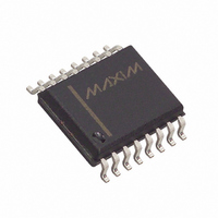
DS1231S-20/T&R Maxim Integrated Products, DS1231S-20/T&R Datasheet - Page 2

DS1231S-20/T&R
Manufacturer Part Number
DS1231S-20/T&R
Description
IC POWER MONITOR 20NS 16-SOIC
Manufacturer
Maxim Integrated Products
Type
Simple Reset/Power-On Resetr
Datasheet
1.DS1231-20.pdf
(9 pages)
Specifications of DS1231S-20/T&R
Number Of Voltages Monitored
1
Output
Open Drain or Open Collector
Reset
Active High/Active Low
Reset Timeout
150 ms Minimum
Voltage - Threshold
4.37V, 4.62V
Operating Temperature
0°C ~ 70°C
Mounting Type
Surface Mount
Package / Case
16-SOIC (0.300", 7.5mm Width)
Lead Free Status / RoHS Status
Contains lead / RoHS non-compliant
OPERATION
The DS1231 Power Monitor detects out-of-tolerance
power supply conditions and warns a processor-based
system of impending power failure. The main elements
of the DS1231 are illustrated in Figure 1. As shown, the
DS1231 actually has two comparators, one for monitor-
ing the input (Pin 1) and one for monitoring V
The V
and RST (Pin 6) when V
as defined by TOL (Pin 3).
When TOL is connected to ground, the RST and RST
signals will become active as V
volts. When TOL is connected to V
signals become active as V
RST and RST signals are excellent control signals for a
microprocessor, as processing is stopped at the last
possible moments of valid V
RST are kept active for a minimum of 150 ms to allow the
power supply to stabilize (see Figure 2).
The comparator monitoring the input pin produces the
NMI signal (Pin 7) when the input threshold voltage
(V
When the Mode pin is connected to V
curs at V
pedance input allowing for a simple resistor voltage di-
vider network to interface with high voltage signals.
When the Mode pin is connected to ground, detection
occurs at V
rent allowing for connection to switched inputs, such as
a UL-approved opto-isolator. The flexibility of the input
pin allows for detection of power loss at the earliest point
in a power supply system, maximizing the amount of
time allotted between NMI and RST. On power-up, NMI
is released as soon as the input threshold voltage (V
is achieved and V
DS1231/S
022698 2/9
TP
) falls to a level as determined by Mode (Pin 2).
CC
TP
comparator outputs the signals RST (Pin 5)
-. In this mode Pin 1 is an extremely high im-
TP
+. In this mode Pin 1 sources 30 A of cur-
CC
is within nominal limits. In both
CC
CC
falls below a preset trip level
CC
goes below 4.5 volts. The
. On power-up, RST and
CC
CC
, the RST and RST
goes below 4.75
CC
, detection oc-
CC
(Pin 8).
TP
)
modes of operation the input pin has hysteresis for
noise immunity (Figure 3).
APPLICATION – MODE PIN
CONNECTED TO V
When the Mode pin is connected to V
impedance input. The voltage sense point and the level
of voltage at the sense point are dependent upon the
application (Figure 4). The sense point may be devel-
oped from the AC power line by rectifying and filtering
the AC. Alternatively, a DC voltage level may be se-
lected which is closer to the AC power input than the
regulated +5-volt supply, so that ample time is provided
for warning before regulation is lost.
Proper operation of the DS1231 requires a maximum
voltage of 5 volts at the input (Pin 1), which must be
derived from the maximum voltage at the sense point.
This is accomplished with a simple voltage divider net-
work of R1 and R2. Since the IN trip point V
volts (using the -20 device), and the maximum allowable
voltage on pin 1 is 5 volts, the dynamic range of voltage
at the sense point is set by the ratio of 2.3/5.0=.46 min.
This ratio determines the maximum deviation between
the maximum voltage at the sense point and the actual
voltage which will generate NMI.
Having established the desired ratio, and confirming
that the ratio is greater than .46 and less than 1, the
proper values for R1 and R2 can be determined by the
equation as shown in Figure 4. A simple approach to
solving this equation is to select a value for R2 which is
high enough impedance to keep power consumption
low, and solve for R1. Figure 5 illustrates how the
DS1231 can be interfaced to the AC power line when
the mode pin is connected to V
CC
CC
.
CC
, pin 1 is a high
TP
- is 2.3


