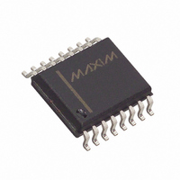
DS1231S-35+ Maxim Integrated Products, DS1231S-35+ Datasheet - Page 5

DS1231S-35+
Manufacturer Part Number
DS1231S-35+
Description
IC POWER MONITOR 35NS 16-SOIC
Manufacturer
Maxim Integrated Products
Type
Simple Reset/Power-On Resetr
Datasheet
1.DS1231-20.pdf
(9 pages)
Specifications of DS1231S-35+
Number Of Voltages Monitored
1
Output
Open Drain or Open Collector
Reset
Active High/Active Low
Reset Timeout
150 ms Minimum
Voltage - Threshold
4.37V, 4.62V
Operating Temperature
0°C ~ 70°C
Mounting Type
Surface Mount
Package / Case
16-SOIC (0.300", 7.5mm Width)
Monitored Voltage
4.5 V to 5.5 V
Undervoltage Threshold
4.5 V
Overvoltage Threshold
4.74 V
Output Type
Active High, Active Low, Open Drain
Manual Reset
Not Resettable
Watchdog
No Watchdog
Battery Backup Switching
No Backup
Supply Voltage (max)
5.5 V
Supply Voltage (min)
4.5 V
Supply Current (typ)
2000 uA
Maximum Operating Temperature
+ 70 C
Mounting Style
SMD/SMT
Minimum Operating Temperature
0 C
Power Fail Detection
Yes
Lead Free Status / RoHS Status
Lead free / RoHS Compliant
APPLICATION – MODE PIN CONNECTED TO
GROUND
When the Mode pin is connected to ground, pin 1 is a
current source of 30 A with a V
held below the trip point by a switching device like an
opto-isolator as shown in Figure 6. Determination of the
sense point has the same criteria as discussed in the
previous application. However, determining component
values is significantly different. In this mode, the maxi-
mum dynamic range of the sense point versus desired
trip voltage is primarily determined by the selection of a
zener diode. As an example, if the maximum voltage at
the sense point is 200V and the desired trip point is
150V, then a zener diode of 150V will approximately set
AC VOLTAGE MONITOR WITH TRANSFORMER ISOLATION Figure 5
NOTE: RST requires a pull–up resister.
TP
+ of 2.5 volts. Pin 1 is
VOLTAGE SENSE POINT
+5V
DC
the trip point. This is particularly true if power consump-
tion on the high voltage side of the opto-isolator is not an
issue. However, if power consumption is a concern,
then it is desirable to make the value of R1 high. As the
value of R1 increases, the effect of the LED current in
the opto-isolator starts to affect the IN trip point. This can
be seen from the equation shown in Figure 6. R1 must
also be low enough to allow the opto-isolator to sink the
30 A of collector current required by pin 1 and still have
enough resistance to keep the maximum current
through the opto-isolator’s LED within data sheet limits.
Figure 7 illustrates how the DS1231 can be interfaced to
the AC power line when the mode pin is grounded.
IN
MODE
TOL
GND
DS1231
RST
RST
V
NMI
CC
-10% V
CC
+5V
THRESHOLD
DC
TO
022698 5/9
DS1231/S
P


