Operating Temperature .................................... -45 °C to +85 °C
Maximum Device Surface Temperature
Passive Aging .................................................. +85 °C, 1000 hours ............................................... ±15 % typical resistance change
Humidity Aging ................................................ +85 °C, 85 % R.H. 1000 hours ............................. ±15 % typical resistance change
Thermal Shock ................................................ MIL-STD-202F, Method 107G, ............................. ±10 % typical resistance change
Solvent Resistance .......................................... MIL-STD-202, Method 215B ................................ No change
Lead Solerability .............................................. ANSI/J-STD-002
Flammability .................................................... IEC 695-2-2 .......................................................... No Flame for 60 secs.
Vibration .......................................................... MIL-STD-883C, Method 2007.1, Condition A ...... No change
Test
Visual/Mech. .................................................... Verify dimensions and materials ...................... Per MF physical description
Resistance ....................................................... In still air @ 23 °C ............................................. Rmin ≤ R ≤ Rmax
Time to Trip ...................................................... At specifi ed current, Vmax, 23 °C ................... T ≤ max. time to trip (seconds)
Hold Current .................................................... 30 min. at Ihold ................................................ No trip
Test
Mains Power Contact - ITU-T K.20, K.21 ........ 230 V rms, 10 ohms, t = 15 min. ..................... None
Power Induction - ITU-T K.20, K.21 ................ 600V rms, 600 ohms, t = 0.2 seconds ............. None
Power Induction - ITU-T K.20, K.21 ................ 600 V rms, 600 ohms, t = 1 second. ............... GDT
Lightning Surge - ITU-T K.20, K.21 ................. 1.5 KV, 10/700 μs ............................................. None
Lightning Surge ............................................... 4.0 KV, 10/700 μs ............................................. GDT
*RoHS Directive 2002/95/EC Jan 27 2003 including Annex.
Specifi cations are subject to change without notice.
Customers should verify actual device performance in their specifi c applications.
* R 1 value is measured 24 hours post refl ow.
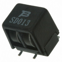
MF-SD013/250
Test Procedures And Requirements For Model MF-SD/250 Series
MF-SD013/250
Resistance matched in housing: 1.0 ohm measured 24 hours after refl ow installation.
Model
Electrical Characteristics
Environmental Characteristics
in Tripped State ............................................ 125 °C
Thermal Derating Chart -I hold (Amps)
..................................................................... +60 °C, 1000 hours ............................................... ±15 % typical resistance change
Model
Operating
Voltage
Max.
Volts
60
-40 °C
0.21
Volts
250
(V)
Interrupt
Ratings
-20 °C
Max.
0.18
Amps
3.0
(A)
+125 °C to -55 °C,10 times
Test Conditions
Test Conditions
Features
■
■
■
■
■
MF-SD/250 Series - Telecom PTC Resettable Fuses
Tip & ring line protection with two devices
in one package
Surface mount device
High voltage surge capabilities
Assists in meeting ITU-T K.20/K.21/K.45
specifi cations as well as Telcordia GR-1089
intra-building
RoHS compliant*
0 °C
0.16
Ihold
0.13
Hold
Amperes
at 23 °C
Asia-Pacifi c: Tel: +886-2 2562-4117 • Fax: +886-2 2562-4116
Europe: Tel: +41-41 768 5555 • Fax: +41-41 768 5510
The Americas: Tel: +1-951 781-5500 • Fax: +1-951 781-5700
www.bourns.com
0.26
Itrip
Trip
Ambient Operating Temperature
23 °C
0.13
Min.
2.0
Resistance
at 23 °C
Ohms
Initial
40 °C
0.10
Max.
7.0
Resistance*
1 Hour (R 1 )
Post-Trip
at 23 °C
50 °C
Ohms
Accept/Reject Criteria
Primary
Protection
0.09
Max.
10.0
±15 % typical resistance change
Applications
Used as a secondary overcurrent protection
device in:
■
■
■
Customer Premise Equipment (CPE)
Central Offi ce (CO)
Subscriber Line Interface Cards (SLIC)
at 23 °C
60 °C
0.08
Amps
1
Nominal Time
to Trip
Seconds
at 23 °C
70 °C
0.07
2.0
Dissipation
at 23 °C
Tripped
85 °C
Power
Watts
0.05
Typ.
1.5


