TISP4080M3LM Bourns Inc., TISP4080M3LM Datasheet - Page 3
TISP4080M3LM
Manufacturer Part Number
TISP4080M3LM
Description
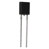
SURGE SUPP THYRISTOR 65V TO-92
Manufacturer
Bourns Inc.
Specifications of TISP4080M3LM
Package / Case
TO-92-2, TO-226AC
Voltage - Breakover
80V
Voltage - Off State
65V
Voltage - On State
3V
Current - Peak Pulse (8 X 20µs)
220A
Current - Peak Pulse (10 X 1000µs)
50A
Current - Hold (ih)
150mA
Number Of Elements
1
Capacitance
120pF
Mounting Style
Through Hole
Lead Free Status / RoHS Status
Lead free / RoHS Compliant
Available stocks
Company
Part Number
Manufacturer
Quantity
Price
Company:

Part Number:
TISP4080M3LM
Manufacturer:
BOURNS
Quantity:
240 000
Company:
Part Number:
TISP4080M3LMFR
Manufacturer:
MAXIM
Quantity:
2 900


The protector consists of a symmetrical voltage-triggered bidirectional thyristor. Overvoltages are initially clipped by breakdown clamping
until the voltage rises to the breakover level, which causes the device to crowbar into a low-voltage on state. This low-voltage on state
causes the current resulting from the overvoltage to be safely diverted through the device. The high crowbar holding current prevents d.c.
latchup as the diverted current subsides.
This TISP4xxxM3LM range consists of seventeen voltage variants to meet various maximum system voltage levels (58 V to 320 V). They are
guaranteed to voltage limit and withstand the listed international lightning surges in both polarities. These protection devices are supplied
in a DO-92 (LM) cylindrical plastic package. The TISP4xxxM3LM is a straight lead DO-92 supplied in bulk pack and on tape and reel. The
TISP4xxxM3LMF is a formed lead DO-92 supplied only on tape and reel. For higher rated impulse currents in the DO-92 package, the 100 A
10/1000 TISP4xxxH3LM series is available.
NOVEMBER 1997 - REVISED JANUARY 2010
Specifi cations are subject to change without notice.
Customers should verify actual device performance in their specifi c applications.
Repetitive peak off-state voltage, (see Note 1)
Non-repetitive peak on-state pulse current (see Notes 2, 3 and 4)
Non-repetitive peak on-state current (see Notes 2, 3 and 5)
Initial rate of rise of on-state current, Exponential current ramp, Maximum ramp value < 100 A
Junction temperature
Storage temperature range
NOTES: 1. See Applications Information and Figure 10 for voltage values at lower temperatures.
Description
Absolute Maximum Ratings, T
TISP4xxxM3LM Overvoltage Protector Series
2/10 µs (GR-1089-CORE, 2/10 µs voltage wave shape)
8/20 µs (IEC 61000-4-5, combination wave generator, 1.2/50 voltage, 8/20 current)
10/160 µs (FCC Part 68, 10/160 µs voltage wave shape)
5/200 µs (VDE 0433, 10/700 µs voltage wave shape)
0.2/310 µs (I 31-24, 0.5/700 µs voltage wave shape)
5/310 µs (ITU-T K.20/21, 10/700 µs voltage wave shape)
5/310 µs (FTZ R12, 10/700 µs voltage wave shape)
5/320 µs (FCC Part 68, 9/720 µs voltage wave shape)
10/560 µs (FCC Part 68, 10/560 µs voltage wave shape)
10/1000 µs (GR-1089-CORE, 10/1000 µs voltage wave shape)
20 ms (50 Hz) full sine wave
16.7 ms (60 Hz) full sine wave
1000 s 50 Hz/60 Hz a.c.
2. Initially the TISP4xxxM3LM must be in thermal equilibrium with T
3. The surge may be repeated after the TISP4xxxM3LM returns to its initial conditions.
4. See Applications Information and Figure 11 for current ratings at other temperatures.
5. EIA/JESD51-2 environment and EIA/JESD51-3 PCB with standard footprint dimensions connected with 5 A rated printed wiring
track widths. See Figure 8 for the current ratings at other durations. Derate current values at -0.61 %/°C for ambient
temperatures above 25 °C
A
= 25 °C (Unless Otherwise Noted)
Rating
J
= 25 °C.
‘4070
‘4080
‘4095
‘4115
‘4125
‘4145
‘4165
‘4180
‘4220
‘4240
‘4250
‘4260
‘4290
‘4300
‘4350
‘4395
‘4400
Symbol
di
V
I
I
T
TSM
DRM
TSP
T
T
stg
/dt
J
-40 to +150
-65 to +150
Value
±100
±120
±135
±145
±160
±180
±190
±200
±220
±230
±275
±320
±300
± 58
± 65
± 75
± 90
300
220
120
110
100
100
100
300
100
2.1
30
32
75
50
A/µs
Unit
°C
°C
V
A
A
Related parts for TISP4080M3LM
Image
Part Number
Description
Manufacturer
Datasheet
Request
R

Part Number:
Description:
Manufacturer:
Bourns, Inc.
Datasheet:
Part Number:
Description:
11mm Potentiometer
Manufacturer:
Bourns, Inc.
Datasheet:
Part Number:
Description:
Manufacturer:
Bourns, Inc.
Datasheet:
Part Number:
Description:
Manufacturer:
Bourns, Inc.
Datasheet:
Part Number:
Description:
Manufacturer:
Bourns, Inc.
Datasheet:
Part Number:
Description:
5/16 Round Trimming Potentiometer
Manufacturer:
Bourns, Inc.
Datasheet:
Part Number:
Description:
4100R Series: Thick Film Moulded DIPs - Resistor Networks
Manufacturer:
Bourns, Inc.
Datasheet:
Part Number:
Description:
PROTECTOR - SINGLE BIDIRECTIONAL
Manufacturer:
Bourns, Inc.