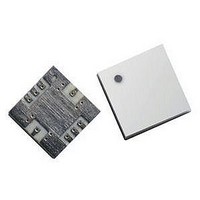
AMMP-5620-TR1G Avago Technologies US Inc., AMMP-5620-TR1G Datasheet - Page 9

AMMP-5620-TR1G
Manufacturer Part Number
AMMP-5620-TR1G
Description
IC MMIC AMP HGA 6-20GHZ 8SMD
Manufacturer
Avago Technologies US Inc.
Datasheet
1.AMMP-5620-TR2G.pdf
(12 pages)
Specifications of AMMP-5620-TR1G
Gain
17.5dB
Rf Type
General Purpose
Current - Supply
95mA
Frequency
6GHz ~ 20GHz
Noise Figure
5.1dB
P1db
14.8dBm
Package / Case
8-SMD
Test Frequency
18GHz
Voltage - Supply
5V
Frequency Range
6GHz To 20GHz
Noise Figure Typ
5.1dB
Power Dissipation Pd
1W
Supply Current
95mA
Supply Voltage Range
5V
Rf Ic Case Style
SMD
Number Of Channels
1
Frequency (max)
20GHz
Power Supply Requirement
Single
Single Supply Voltage (typ)
5V
Package Type
SMT
Dual Supply Voltage (min)
Not RequiredV
Dual Supply Voltage (typ)
Not RequiredV
Dual Supply Voltage (max)
Not RequiredV
Pin Count
8
Mounting
Surface Mount
Lead Free Status / RoHS Status
Lead free / RoHS Compliant
Lead Free Status / RoHS Status
Lead free / RoHS Compliant, Lead free / RoHS Compliant
Available stocks
Company
Part Number
Manufacturer
Quantity
Price
Part Number:
AMMP-5620-TR1G
Manufacturer:
AVAGO/安华高
Quantity:
20 000
Biasing and Operation
The AMMP-5620 only requires a single positive supply
connected to the Vd pin (2). The recommended supply
voltage is 5V. The supply should be bypassed with a 0.1uF
capacitor placed as close to the component as possible.
The package base is the RF and DC ground connection.
The biasing arrangement is shown in Figure 21.
Figure 22 shows a simplifies schematic for the amplifier
die. All three stages are self-biased as shown. Each stage
has feedback around it to control the gain, match and
performance, resulting in excellent wideband perfor-
mance. Also shown are the on-chip DC blocking capaci-
tors for both the RFin and RFout pins.
Please refer to the Absolute Maximum Ratings table for
allowed DC and thermal conditions.
9
Figure 21. Typical Application.
Figure 22. Simplified MMIC Schematics.
Recommended SMT Attachment
The AMMP Packaged Devices are compatible with high
volume
surface mount PCB assembly processes. The PCB material
and mounting pattern, as defined in the data sheet,
optimizes RF performance and is strongly recommend-
ed. An electronic drawing of the land pattern is available
upon request from Avago Sales & Application Engineer-
ing.
Figure 23. Demonstration Board (available upon request).


