ATAB5428-8-WB Atmel, ATAB5428-8-WB Datasheet - Page 59
ATAB5428-8-WB
Manufacturer Part Number
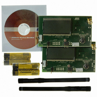
ATAB5428-8-WB
Description
KIT DEMO 868MHZ BLACKBIRD
Manufacturer
Atmel
Series
Smart RFr
Type
Transceiver, UHFr
Specifications of ATAB5428-8-WB
Frequency
868MHz
Maximum Frequency
868 MHz
Output Power
0 dBm to 10 dBm
Supply Voltage (max)
6 V
Supply Voltage (min)
3 V
Supply Current
21 mA
Maximum Operating Temperature
+ 85 C
Board Size
2 in x 3.5 in
Minimum Operating Temperature
- 40 C
Product
RF Modules
For Use With/related Products
ATA5428
Lead Free Status / RoHS Status
Lead free / RoHS Compliant
Other names
ATAB-5428-8-WB


9.1.7
Figure 9-8.
4841D–WIRE–10/07
Receiving Mode
SDO_TMDO
Demod_Out
Receiving Mode (TMODE = 1)
'0' '0' '0' '0' '0' '0' '0' '0' '0' '1'
Bit-check mode
In the presence of a valid transmitter signal, T
nal, f
longer period for T
If the bit check was successful for all bits specified by N
receiving mode. To activate a connected microcontroller, the bits VSOUT_EN and CLK_ON in
control register 3 are set to “1”. An interrupt is issued at pin IRQ if the control bits T_MODE = 0
and P_MODE = 0.
If the transparent mode is active (T_MODE = 1) and the level on pin CS is low (no data transfer
via the serial interface), the RX data stream is available on pin SDO_TMDO
If the transparent mode is inactive (T_MODE = 0), the received data stream is buffered in the
TX/RX data buffer (see
Manchester and Bi-phase coded signals. It is always possible to transfer the data from the data
buffer via the 4-wire serial interface to a microcontroller (see
Buffering of the data stream:
After a successful bit check, the transceiver switches from bit-check mode to receiving mode. In
receiving mode the TX/RX data buffer control logic is active and examines the incoming data
stream. This is done, as in the bit check, by subsequent time frame checks where the distance
between two edges is continuously compared to a programmable time window as illustrated in
Figure 9-9 on page
Bi-phase coded signals are valid (T and 2T).
The limits for T are the same as used for the bit check. They can be programmed in control
register 5 and 6 (Lim_min, Lim_max).
The limits for 2T are calculated as follows:
Lower limit of 2T:
Upper limit of 2T:
If the result of Lim_min_2T or Lim_max_2T is not an integer value, it will be rounded up.
Lim_min_2T
T
Lim_max_2T
T
Lim_min_2T
Lim_max_2T
Signal
, and the count of the bits, N
=
=
=
=
Lim_min_2T
Lim_max_2T - 1
Lim_min
Lim_min
Bit-check
60. Only two time differences between two edges in Manchester and
ATA5423/ATA5425/ATA5428/ATA5429
+
'0'
+
, requiring a higher value for the transmitter pre-burst, T
Lim_max
Figure 9-9 on page
Lim_max
'1'
T
XDCLK
'0' '0' '0' '0' '0' '1' '1' '1' '1' '0' '0' '1' '1' '0' '1' '0' '1' '1' '0' '0'
T
Receiving mode
XDCLK
–
+
Lim_max Lim_min
Lim_max Lim_min
Bit-check
. A higher value for N
–
Bit-check
–
60). The TX/RX data buffer is only usable for
is dependent on the frequency of that sig-
/2
/2
Bit-check
Figure 8-1 on page
, the transceiver switches to
Bit-check
therefore results in a
(Figure
49).
Preburst
9-8).
.
59
Related parts for ATAB5428-8-WB
Image
Part Number
Description
Manufacturer
Datasheet
Request
R


Part Number:
Description:
KIT DEMO 434MHZ BLACKBIRD
Manufacturer:
Atmel
Datasheet:

Part Number:
Description:
BOARD BASESTATN UHF RCVR 433MHZ
Manufacturer:
Atmel
Datasheet:
Part Number:
Description:
BOARD BASESTATN UHF RCVR 868MHZ
Manufacturer:
Atmel
Datasheet:

Part Number:
Description:
DEV KIT FOR AVR/AVR32
Manufacturer:
Atmel
Datasheet:

Part Number:
Description:
INTERVAL AND WIPE/WASH WIPER CONTROL IC WITH DELAY
Manufacturer:
ATMEL Corporation
Datasheet:
Part Number:
Description:
Low-Voltage Voice-Switched IC for Hands-Free Operation
Manufacturer:
ATMEL Corporation
Datasheet:
Part Number:
Description:
MONOLITHIC INTEGRATED FEATUREPHONE CIRCUIT
Manufacturer:
ATMEL Corporation
Datasheet:
Part Number:
Description:
AM-FM Receiver IC U4255BM-M
Manufacturer:
ATMEL Corporation
Datasheet:
Part Number:
Description:
Monolithic Integrated Feature Phone Circuit
Manufacturer:
ATMEL Corporation
Datasheet:
Part Number:
Description:
Multistandard Video-IF and Quasi Parallel Sound Processing
Manufacturer:
ATMEL Corporation
Datasheet:
Part Number:
Description:
High-performance EE PLD
Manufacturer:
ATMEL Corporation
Datasheet: