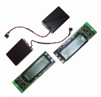
ATR2406-DEV-KIT2 Atmel, ATR2406-DEV-KIT2 Datasheet - Page 4

ATR2406-DEV-KIT2
Manufacturer Part Number
ATR2406-DEV-KIT2
Description
KIT DEMO FOR ATR2406/ATMEGA88
Manufacturer
Atmel
Series
Smart RFr
Type
Transceiver, ISMr
Datasheet
1.ATR2406-DEV-BOARD.pdf
(25 pages)
Specifications of ATR2406-DEV-KIT2
Frequency
2.4GHz
Wireless Frequency
2.4 GHz
Interface Type
SPI
Modulation
GFSK
Operating Voltage
2.9 V to 3.6 V
Operating Temperature Range
- 10 C to + 60 C
For Use With/related Products
ATR2406
Lead Free Status / RoHS Status
Contains lead / RoHS non-compliant
3. Functional Description
3.1
3.2
3.3
3.4
3.5
4
Receiver
Clock Recovery
Transmitter
Synthesizer
Power Supply
ATR2406
The RF signal at RF_IN is differentially fed through the LNA to the image rejection mixer
IR_MIXER, driving the integrated low-IF band-pass filter. The IF frequency is 864 kHz. The limit-
ing IF_AMP with an integrated RSSI function feeds the signal to the digital demodulator
DEMOD. No tuning is required. Data slicing is handled internally.
For a 1152-kBit/s data rate, the receiver has a clock recovery function on-chip.
The receiver includes a clock recovery circuit which regenerates the clock out of the received
data. The advantage is that this recovered clock is synchronous to the clock of the transmitting
device (and thus to the transmitted data), which significantly reduces the load of the processing
microcontroller.
The falling edge of the clock is the optimal sampling position for the RX_Data signal, so at this
event the data must be sampled by the microcontroller. The recovered clock is available at pin 6.
The transmit data at TX_DATA is filtered by an integrated Gaussian filter (GF) and fed to the
fully integrated VCO operating at twice the output frequency. After modulation, the signal is fre-
quency divided by 2 and fed to the internal preamplifier PA. This preamplifier supplies typically
+4 dBm output power at TX_OUT.
A ramp-signal generator RAMP_GEN, providing a ramp signal at RAMP_OUT for the external
power amplifier, is integrated. The slope of the ramp signal is controlled internally so that spuri-
ous requirements are fulfilled.
The IR_MIXER, the PA, and the programmable counter (PC) are driven by the fully integrated
VCO, using on-chip inductors and varactors. The output signal is frequency divided to supply the
desired frequency to the TX_DRIVER, the 0/90 degree phase shifter for the IR_MIXER, and to
be used by the PC for the phase detector (PD) (f
supported.
An integrated band-gap–stabilized voltage regulator for use with an external low-cost PNP tran-
sistor is implemented. Multiple power-down and current saving modes are provided.
PD
= 1.728 MHz). Open loop modulation is
4779N–ISM–12/08


