DVK-BTM521 Laird Technologies, DVK-BTM521 Datasheet - Page 64
DVK-BTM521
Manufacturer Part Number
DVK-BTM521
Description
BT MM DEV KIT
Manufacturer
Laird Technologies
Type
Transceiver, Bluetoothr
Specifications of DVK-BTM521
Frequency
2.4GHz
Interface Type
RS-232
Processor Series
BTM521
Silicon Manufacturer
Laird Technologies
Kit Application Type
Communication & Networking
Application Sub Type
Bluetooth
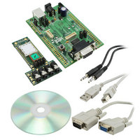
Kit Contents
Development Board & Software Tools
Features
Supports CSR
Rohs Compliant
Yes
For Use With/related Products
BTM521
Lead Free Status / RoHS Status
Lead free / RoHS Compliant
Lead Free Status / RoHS Status
Lead free / RoHS Compliant, Lead free / RoHS Compliant
Other names
DVK-BTM521
Available stocks
Company
Part Number
Manufacturer
Quantity
Price
Company:

Part Number:
DVK-BTM521-01
Manufacturer:
LAIRD
Quantity:
7


BTM520/521
Bluetooth
AT COMMAND SET
REFERENCE
64 www.lairdtech.com
®
Multimedia Plus Module
7.1.10 Enable Caller Line Identification Presentation – CLIP (#13_4.23)
7.1.11 Enable Call Waiting Notification – CCWA (#11_4.21)
7.1.5 Answer Incoming Call from HF (#4_4.13)
7.1.6 Reject Incoming Call from HF/Terminate Call from HF (#5_4.14;#6_4.15)
7.1.7 Place Call with Number Provided by HF (#8_4.18)
7.1.8 Memory Dialing from the HF (#9_4.19)
7.1.9 Re-Dial Last Number from HF (#10_4.20)
AT+HFCA
Answer an incoming call. “ATA” will be sent to the AG. In return, the audio gateway shall
update its “+CIEV” indicators (“call=1” and “callsetup=0”) and send appropriate messages to
the HF. Upon receipt of a “+CIEV” message, HF will notify its host by a “HFI<indicator>,<value>”
message. Please refer to section 7.1.15 on page 66.
AT+HFCH
Reject incoming call / terminate ongoing call. “AT+CHUP” will be sent to the AG. In return,
the audio gateway shall update its indicator “call”=0 and send the appropriate “+CIEV”
message to the HF. HF will notify its host by a “HFI<indicator>,<value>” message. Please
refer to section 7.1.15 on page 66.
AT+HFC”nnn”
Initiate a new call from HF to the number specified by the number string “nnn”.
This command will send “ATDnnn” to the audio gateway.
AT+HFCM”mmm”
Initiate a new call from HF to the number stored in memory location “mmm” of the AG.
This command will send “ATD>mmm” to the audio gateway.
AT+HFCL
Initiate a new call from HF to the number last dialled by AG. “AT+BLDN” will be sent to the
AG. In return, the audio gateway shall update its indicator “callsetup”=2 and send the
appropriate “+CIEV” message to the HF. HF will notify its host by a “HFI<indicator>,<value>”
message. Please refer to section 7.1.15 on page 66.
The CLIP feature is enabled by setting Bit 2 (value=4) in the HF supported features S
register 581. Subsequent AT&W and ATZ is required to take effect. If this bit is set at boot
time, the following actions are carried out automatically:
Response to action no. 3 will be indicated by either HF”CLIP,OK” or HF”CLIP,ERROR” after
the “CONNECT…” message.
The CCWA feature is enabled by setting Bit 1 (value=2) in the HF supported features S
register 581. Subsequent AT&W and ATZ is required to take effect. If this bit is set at boot
time, the following actions are carried out automatically:
Response to action no. 3 will be indicated by either HF”CCWA,OK” or HF”CCWA,ERROR”
after the “CONNECT…” message.
1. The according flag is set in the HF service record.
2. The according flag is set in the BRSF-message on Service Level Connection establishment
3. The SLC message “AT+CLIP=1” is sent automatically once the SLC is established
1. The according flag is set in the HF service record.
2. The according flag is set in the BRSF-message on Service Level Connection establishment
3. The SLC message “AT+CCWA=1” is sent automatically once the SLC is established
Laird Technologies
Related parts for DVK-BTM521
Image
Part Number
Description
Manufacturer
Datasheet
Request
R

Part Number:
Description:
BLUETOOTH EVAL BOARD BTM511
Manufacturer:
Laird Technologies
Datasheet:

Part Number:
Description:
Bluetooth / 802.15.1 Modules & Development Tools BLUETTH AT Data MODLE, No ANT DEVKIT
Manufacturer:
Laird Technologies
Part Number:
Description:
Bluetooth / 802.15.1 Modules & Development Tools BLUETTH Multimed MODLE, No ANT DEVKIT
Manufacturer:
Laird Technologies
Datasheet:

Part Number:
Description:
BLUETOOTH MODULE DEVELOPMENT KIT
Manufacturer:
Laird Technologies
Part Number:
Description:
Bluetooth 2.0 AT Data Module, Internal Antenna Development Kit
Manufacturer:
Laird Technologies
Part Number:
Description:
Bluetooth / 802.15.1 Modules & Development Tools BLUETTH HCI Data MDLE INTRNLANT DVKIT
Manufacturer:
Laird Technologies
Datasheet:
Part Number:
Description:
Bluetooth / 802.15.1 Modules & Development Tools BLUETTHMultimedMODLE Plus No Ant DEVKIT
Manufacturer:
Laird Technologies
Part Number:
Description:
Bluetooth / 802.15.1 Modules & Development Tools BLUETTH HCI Data MDLE No ANT DVKIT
Manufacturer:
Laird Technologies
Datasheet:

Part Number:
Description:
KIT FOR PRM113
Manufacturer:
Laird Technologies
Datasheet:

Part Number:
Description:
DEV KIT PRM122
Manufacturer:
Laird Technologies
Datasheet:
Part Number:
Description:
DEV KIT PRM123
Manufacturer:
Laird Technologies
Datasheet:

Part Number:
Description:
KIT FOR PRM112
Manufacturer:
Laird Technologies
Datasheet:
Part Number:
Description:
DEV KIT PRM121
Manufacturer:
Laird Technologies
Datasheet:

Part Number:
Description:
KIT DEVELOPMENT FOR LT2510 U.FL
Manufacturer:
Laird Technologies
Datasheet:

Part Number:
Description:
Bluetooth / 802.15.1 Modules Class2 v2.1+EDR Kit AT Data, Int Ant,SSP
Manufacturer:
Laird Technologies Wireless M2M
Datasheet: