AC164105 Microchip Technology, AC164105 Datasheet - Page 24
AC164105
Manufacturer Part Number
AC164105
Description
MODULE RCVR RFPIC 433MHZ (PKG/5)
Manufacturer
Microchip Technology
Type
Receiverr
Specifications of AC164105
Frequency
433MHz
Wireless Frequency
433.92 MHz
Modulation
ASK
For Use With/related Products
PICkit™ 1
Lead Free Status / RoHS Status
Lead free / RoHS Compliant
Lead Free Status / RoHS Status
Lead free / RoHS Compliant, Lead free / RoHS Compliant


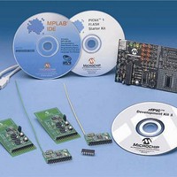
rfPIC™ Development Kit 1 User’s Guide
DS70093A-page 20
4.3.1
Pwr Sel jumper P1 selects one of two power sources for the rfPIC12F675:
• PICkit™ Starter Kit position (pins 1 and 2) – placing a jumper in the PICkit position
• Batt position (pins 2 and 3) – placing a jumper in the batt position allows the
4.3.2
The rfPIC12F675 can be programmed by the PICkit 1 FLASH Starter kit.
Step 1:
Remove the PIC16F676 or PIC12F676 from the PICkit Starter Kit Evaluation Socket.
Step 2:
Plug the transmitter module into the PICkit Starter Kit expansion header J3
(See Figure 4-2).
Step 3:
The internal PIC12F675 in the rfPIC device now becomes the target programming
device. Operate the PICkit Starter Kit in accordance with the steps outlined in the
PICkit™ 1 FLASH Starter Kit User’s Guide.
The transmitter module can be removed for stand-alone operation. Remember to set
the Pwr Sel jumper for each mode of operation (See Power Requirements section
above).
4.3.3
Socket U2 is an unpopulated 8-pin DIP connection on the transmitter module. A
user-provided 8-pin IC socket can be soldered in place.
To use socket U2, the user must disconnect the internal PIC12F675 PICmicro
microcontroller internal to the rfPIC12F675 device from the circuits on the module. This
is done by cutting six PCB traces marked by silk-screened “x”.
Socket U2 can be used for:
• In Circuit Emulation (ICE) with an MPLAB
• Inserting an 8-pin DIP version of the PIC12F675. The DIP PICmicro microcontroller
A detailed description of the rfPIC12F675K/675F/675H microcontroller with UHF
ASK/FSK transmitter is provided in the data sheet, DS70091.
A detailed description of the rfPIC12F675K/675 transmitter module antenna design is
provided in the application note, AN868.
allows the transmitter module to be powered from connector P2 pin 13. When the
transmitter module is plugged in the PICkit expansion header J3, the transmitter
module is powered from the PICkit Starter Kit.
transmitter model to be powered from the lithium coin cell battery. When powered
from the battery, the transmitter module can be used in portable operation.
can be programmed externally (such as a PICSTART
internally via the PICkit Starter Kit.
Note: When programming the transmitter module in the PICkit Starter Kit, the Pwr
Note: There will be some interaction with the LEDs on the PICkit Starter Kit and
Power Requirements
Programming the rfPIC12F675
Optional 8-pin Socket U2
Sel jumper P1 must be in the PICkit position (pins 1 and 2 jumpered).
the rfPIC12F675. If the user desires, the LEDs can be removed from the
circuit by clipping resistors R5, R6, R7, and R8.
Preliminary
®
ICE-2000 and ICD2.
®
Plus or PRO MATE
© 2003 Microchip Technology Inc.
®
II) or
®
Related parts for AC164105
Image
Part Number
Description
Manufacturer
Datasheet
Request
R

Part Number:
Description:
Manufacturer:
Microchip Technology Inc.
Datasheet:
Part Number:
Description:
Manufacturer:
Microchip Technology Inc.
Datasheet:
Part Number:
Description:
Manufacturer:
Microchip Technology Inc.
Datasheet:
Part Number:
Description:
Manufacturer:
Microchip Technology Inc.
Datasheet:
Part Number:
Description:
Manufacturer:
Microchip Technology Inc.
Datasheet:
Part Number:
Description:
Manufacturer:
Microchip Technology Inc.
Datasheet:
Part Number:
Description:
Manufacturer:
Microchip Technology Inc.
Datasheet:
Part Number:
Description:
Manufacturer:
Microchip Technology Inc.
Datasheet: