ATAB5425-3-WB Atmel, ATAB5425-3-WB Datasheet - Page 52
ATAB5425-3-WB
Manufacturer Part Number
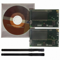
ATAB5425-3-WB
Description
KIT DEMO 345MHZ BLACKBIRD
Manufacturer
Atmel
Type
Transceiver, UHFr
Specifications of ATAB5425-3-WB
Frequency
345MHz
Product
RF Modules
For Use With/related Products
ATA5425
Lead Free Status / RoHS Status
Lead free / RoHS Compliant
Other names
ATAB-5425-3-WB


9. Operation Modes
9.1
9.1.1
52
RX Operation
ATA5423/ATA5425/ATA5428/ATA5429
RX Polling Mode
The transceiver is set to RX operation with the bits OPM0 and OPM1 in control register 1.
Table 9-1.
The transceiver is designed to consume less than 1 mA in RX operation while remaining sensi-
tive to signals from a corresponding transmitter. This is achieved via the polling circuit. This
circuit enables the signal path periodically for a short time. During this time the bit-check logic
verifies the presence of a valid transmitter signal. Only if a valid signal is detected does the
transceiver remain active and transfer the data to the connected microcontroller. This transfer
takes place either via the TX/RX data buffer or via the pin SDO_TMDO. When there is no valid
signal present, the transceiver is in sleep mode most of the time, resulting in low current con-
sumption. This condition is called RX polling mode. A connected microcontroller can be disabled
during this time.
All relevant parameters of the polling logic can be configured by the connected microcontroller.
This flexibility enables the user to meet the specifications in terms of current consumption, sys-
tem response time, data rate, etc.
In RX mode the RF transceiver is enabled permanently and the bit-check logic verifies the pres-
ence of a valid transmitter signal. When a valid signal is detected the transceiver transfers the
data to the connected microcontroller. This transfer take place either via the TX/RX data buffer
or via the pin SDO_TMDO.
When the transceiver is in RX polling mode it stays in a continuous cycle of three different
modes. In sleep mode the RF transceiver is disabled for the time period T
low current of I
cessing circuits are enabled and settled. In the following bit-check mode, the incoming data
stream is analyzed bit by bit to see if it is a valid transmitter signal. If no valid signal is present,
the transceiver is set back to sleep mode after the period T
check as it is a statistical process. An average value for T
teristics. During T
and T
on pin RX_ACTIVE (see
rent consumption in RX polling mode I
application (6V) or Base-station Application (5V). To calculate I
by VS1,VS2 in 1 Li battery application (3V), VS2 in 2 Li battery application (6V) or VS2,VAUX in
Base-station Application (5V) (see section
I
P
=
I
-------------------------------------------------------------------------------------------------------------------------------------------------------------------------------------------------------------------------- -
IDLE_X
Bit-check
OPM1
the current consumption is I
1
1
T
Control Register 1
S
Sleep
= I
Startup_PLL
IDLE_X
+
T
I
Sleep
Startup_PLL_X
. During the start-up period, T
Figure 9-1 on page 54
+
T
the current consumption is I
Startup_PLL
T
Startup_PLL
+
P
OPM0
T
is different in 1 Li battery application (3V), 2 Li battery
S
Startup_Sig_Proc
0
1
“Electrical Characteristics: General” on page
= I
+
RX_X
I
RX_X
and
. The condition of the transceiver is indicated
Figure 9-2 on page
Startup_PLL
+
T
T
Startup_Sig_Proc
S
Bit-check
Bit_check
= I
Bit-check
Startup_PLL_X
and T
P
is given in the electrical charac-
the index X must be replaced
. This period varies check by
RX polling mode
Startup_Sig_Proc
+
T
Function
RX mode
. During T
Bitcheck
55). The average cur-
Sleep
while consuming
4841D–WIRE–10/07
, all signal pro-
Startup_Sig_Proc
67).
Related parts for ATAB5425-3-WB
Image
Part Number
Description
Manufacturer
Datasheet
Request
R

Part Number:
Description:
DEV KIT FOR AVR/AVR32
Manufacturer:
Atmel
Datasheet:

Part Number:
Description:
INTERVAL AND WIPE/WASH WIPER CONTROL IC WITH DELAY
Manufacturer:
ATMEL Corporation
Datasheet:
Part Number:
Description:
Low-Voltage Voice-Switched IC for Hands-Free Operation
Manufacturer:
ATMEL Corporation
Datasheet:
Part Number:
Description:
MONOLITHIC INTEGRATED FEATUREPHONE CIRCUIT
Manufacturer:
ATMEL Corporation
Datasheet:
Part Number:
Description:
AM-FM Receiver IC U4255BM-M
Manufacturer:
ATMEL Corporation
Datasheet:
Part Number:
Description:
Monolithic Integrated Feature Phone Circuit
Manufacturer:
ATMEL Corporation
Datasheet:
Part Number:
Description:
Multistandard Video-IF and Quasi Parallel Sound Processing
Manufacturer:
ATMEL Corporation
Datasheet:
Part Number:
Description:
High-performance EE PLD
Manufacturer:
ATMEL Corporation
Datasheet:
Part Number:
Description:
8-bit Flash Microcontroller
Manufacturer:
ATMEL Corporation
Datasheet:
Part Number:
Description:
2-Wire Serial EEPROM
Manufacturer:
ATMEL Corporation
Datasheet: