ATAB5425-3-WB Atmel, ATAB5425-3-WB Datasheet - Page 60
ATAB5425-3-WB
Manufacturer Part Number
ATAB5425-3-WB
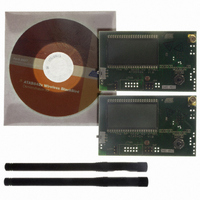
Description
KIT DEMO 345MHZ BLACKBIRD
Manufacturer
Atmel
Type
Transceiver, UHFr
Specifications of ATAB5425-3-WB
Frequency
345MHz
Product
RF Modules
For Use With/related Products
ATA5425
Lead Free Status / RoHS Status
Lead free / RoHS Compliant
Other names
ATAB-5425-3-WB


Figure 9-9.
60
ATA5423/ATA5425/ATA5428/ATA5429
Demod_Out
Receiving Mode (TMODE = 0)
'0' '0' '0' '0' '0' '0' '0' '0' '0' '1'
Bit-check mode
If the TX/RX data buffer control logic detects the start bit, the data stream is written in the TX/RX
data buffer byte by byte. The start bit is part of the first data byte and must be different from the
bits of the preburst. If the preburst consists of a sequence of “00000...”, the start bit must be a
“1”. If the preburst consists of a sequence of “11111...”, the start bit must be a “0”.
If the data stream consists of more than 16 bytes, a buffer overflow occurs and the TX/RX data
buffer control logic overwrites the bytes already stored in the TX/RX data buffer. Therefore, it is
very important to ensure that the data is read in time so that no buffer overflow occurs (see
ure 8-1 on page
data buffer (see section
microcontroller, the counter is decremented; if a byte is received, the counter is incremented.
The counter value is available via the 4-wire serial interface.
An interrupt is issued if the counter (while counting up) reaches the value defined by the control
bits IR0 and IR1 in control register 1.
If the TX/RX data buffer control logic detects a bit error, an interrupt is issued and the transceiver
is set back to the start-up mode (see
Figure 9-10 on page
Bit error:
Note:
Writing the control register 1, 4, 5 or 6 during receiving mode resets the TX/RX data buffer con-
trol logic and the counter which indicates the number of received bytes. If the bits OPM0 and
OPM1 are still “1” after writing to a control register, the transceiver changes to the start-up mode
(start-up signal processing).
The byte consisting of the bit error will not be stored in the TX/RX data buffer. Thus, it is not avail-
able via the 4
a) t
b) Logical error (no edge detected in the bit center)
49). There is a counter that indicates the number of received bytes in the TX/RX
ee
< T
-
wire serial interface.
61).
Lim_min
'0'
“Transceiver Configuration” on page
'1'
'0' '0' '0' '0'
1
1
or T
1
0
1
1
1
0
Lim_max
0
0
0
0
Figure 9-1 on page
1
0
'0' '1' '1' '1' '1' '0' '0' '1' '1' '0' '1' '0' '1' '1' '0' '0'
Receiving mode
1
0
< t
Byte 16, Byte 32, ...
Byte 15, Byte 31, ...
Byte 14, Byte 30, ...
Byte 13, Byte 29, ...
Byte 12, Byte 28, ...
Byte 11, Byte 27, ...
Byte 10, Byte 26, ...
Byte 9, Byte 25, ...
Byte 8, Byte 24, ...
Byte 7, Byte 23, ...
Byte 6, Byte 22, ...
Byte 5, Byte 21, ...
Byte 4, Byte 20, ...
Byte 3, Byte 19, ...
Byte 2, Byte 18, ...
Byte 1, Byte 17, ...
ee
< T
Lim_min_2T
54,
or t
Figure 9-2 on page 55
ee
49). If a byte is transferred to the
> T
Lim_max_2T
4841D–WIRE–10/07
and
Fig-
Related parts for ATAB5425-3-WB
Image
Part Number
Description
Manufacturer
Datasheet
Request
R

Part Number:
Description:
DEV KIT FOR AVR/AVR32
Manufacturer:
Atmel
Datasheet:

Part Number:
Description:
INTERVAL AND WIPE/WASH WIPER CONTROL IC WITH DELAY
Manufacturer:
ATMEL Corporation
Datasheet:
Part Number:
Description:
Low-Voltage Voice-Switched IC for Hands-Free Operation
Manufacturer:
ATMEL Corporation
Datasheet:
Part Number:
Description:
MONOLITHIC INTEGRATED FEATUREPHONE CIRCUIT
Manufacturer:
ATMEL Corporation
Datasheet:
Part Number:
Description:
AM-FM Receiver IC U4255BM-M
Manufacturer:
ATMEL Corporation
Datasheet:
Part Number:
Description:
Monolithic Integrated Feature Phone Circuit
Manufacturer:
ATMEL Corporation
Datasheet:
Part Number:
Description:
Multistandard Video-IF and Quasi Parallel Sound Processing
Manufacturer:
ATMEL Corporation
Datasheet:
Part Number:
Description:
High-performance EE PLD
Manufacturer:
ATMEL Corporation
Datasheet:
Part Number:
Description:
8-bit Flash Microcontroller
Manufacturer:
ATMEL Corporation
Datasheet:
Part Number:
Description:
2-Wire Serial EEPROM
Manufacturer:
ATMEL Corporation
Datasheet: