MDEV-LICAL-MT Linx Technologies Inc, MDEV-LICAL-MT Datasheet - Page 4
MDEV-LICAL-MT
Manufacturer Part Number
MDEV-LICAL-MT
Description
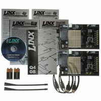
KIT MASTER DEV MT SERIES
Manufacturer
Linx Technologies Inc
Series
MTr
Type
Transcoderr
Specifications of MDEV-LICAL-MT
Supply Voltage (min)
7 V
Product
RF Development Tools
Supply Voltage (max)
16 V
Lead Free Status / RoHS Status
Lead free / RoHS Compliant
For Use With/related Products
MT Series Transcoder
Lead Free Status / Rohs Status
Lead free / RoHS Compliant


THE TRANSCODER AREA (CONT)
THE RF AREA
Page 6
Figure 4: The RF Area
Beneath the LEDs is a button that is connected to the CRT/LRN line. This button
is used to create the Address, set the Control Permissions, and learn an address
as described in the MT Series Transcoder Data Guide.
Next to the CRT/LRN button is a button connected to the ENC_SEL line. This
button is used with the CRT/LRN button to create the Address and set the
Control Permissions. Next to the button is a switch that will take the ENC_SEL
line high so that the transcoder can be placed into Encoder Only mode. If the
switch is up, then the line is controlled by the button. If the switch is down, then
the line is connected to Vcc.
The figure below shows the RF area of the development board.
This board uses the LT Series transceiver for the wireless link. R1 is connected
to the LADJ line of the transceiver to reduce the output power to the approximate
limit of Part 15.231 of the FCC regulations. For applications where Part 15 limits
are not applicable or output levels can be legally raised, R1 can be changed
according to the graph on Page 4 of the LT Series Transceiver Data Guide.
The three switches below the transceiver connect the TR_DATA, TR_SEL and
TR_PDN lines to either the transceiver or the break out header in the Prototyping
Area. This will prevent collisions on the lines resulting from connecting the
transcoder, transceiver, and external circuitry to the same lines. If the switches
are to the left, then the transcoder is connected to the header; if they are to the
right, the transcoder is connected to the tranceiver. Pads have been placed for
LEDs to indicate the states of the TR_SEL and PDN lines. These indicators can
be useful for debugging during development, but have been left to the user to
populate if desired.
MT SERIES MASTER DEVELOPMENT SYSTEM SOFTWARE
Figure 5: The MT Series Master Development System Software
The MS Series Master Development System software can be used in one of two
modes. The default mode provides basic control of the transcoder through the
serial interface engine.
The second mode is for full development of software designed to control the
transcoder through the SIE. It shows all of the commands, the packets sent to
the transcoder and the responses from the transcoder as well as a full view of
the transcoder’s memory bank. This allows full access and control of the
transcoder, aiding in product development.
Both modes interface to the development boards through the USB module,
demonstrating the simplicity of the hardware / software interface. Clicking a
button on one computer causes the development board to activate, sending a
command to the other development board. The other board then outputs the
command to another computer where an action takes place, demonstrating the
power and simplicity of the MT Series system.
Page 7
Related parts for MDEV-LICAL-MT
Image
Part Number
Description
Manufacturer
Datasheet
Request
R

Part Number:
Description:
DEV SYSTEM MS SERIES 418MHZ
Manufacturer:
Linx Technologies Inc
Datasheet:

Part Number:
Description:
DEV SYSTEM HS SERIES 418MHZ
Manufacturer:
Linx Technologies Inc
Datasheet:

Part Number:
Description:
KIT MASTER 900MHZ HP-3 SIP RS232
Manufacturer:
Linx Technologies Inc
Datasheet:

Part Number:
Description:
KIT MASTER DEV 916MHZ ES RS232
Manufacturer:
Linx Technologies Inc
Datasheet:

Part Number:
Description:
KIT DEV MASTER USB QS SERIES
Manufacturer:
Linx Technologies Inc
Datasheet:

Part Number:
Description:
KIT MASTER DEV MS KEYFOB 418MHZ
Manufacturer:
Linx Technologies Inc
Datasheet:

Part Number:
Description:
KIT DEV MS HANDHELD TX 418MHZ
Manufacturer:
Linx Technologies Inc
Datasheet:
Part Number:
Description:
KIT MASTER DEV MS KEYFOB 433MHZ
Manufacturer:
Linx Technologies Inc
Datasheet:

Part Number:
Description:
KIT DEV TX 433MHZ HS COMPACT
Manufacturer:
Linx Technologies Inc
Datasheet:

Part Number:
Description:
KIT DEV TX 418MHZ HS COMPACT
Manufacturer:
Linx Technologies Inc
Datasheet:

Part Number:
Description:
MODULE USB LOW SPEED
Manufacturer:
Linx Technologies Inc
Datasheet:

Part Number:
Description:
IC TRANSCODER MT BI-DIR 20-SSOP
Manufacturer:
Linx Technologies Inc
Datasheet:

Part Number:
Description:
IC ENCODER LOW SECURITY 8DIP
Manufacturer:
Linx Technologies Inc
Datasheet:

Part Number:
Description:
IC DECODER MS SERIES 20-SSOP
Manufacturer:
Linx Technologies Inc
Datasheet:
Part Number:
Description:
IC ENCODER MS SERIES 20-SSOP
Manufacturer:
Linx Technologies Inc
Datasheet: